
Method and apparatus for improving the leveling performance of an elevator

a technology of elevator system and leveling requirements, applied in the direction of elevators, transportation and packaging, etc., can solve the problems of increasing the length of suspension members and loosening their balance, and achieve the effect of minimizing re-leveling

Inactive Publication Date: 2005-10-20
THYSSENKRUPP ELEVATOR CAPITAL CORP
View PDF12 Cites 49 Cited by
  • Summary
  • Abstract
  • Description
  • Claims
  • Application Information

AI Technical Summary

Benefits of technology

[0007] The invention provides an elevator position compensation system that minimizes the re-leveling of an elevator car in an elevator shaft. The elevator car is suspended in the shaft by an elevator cable system that is driven by an elevator motor. The elevator position compensation system comprises an elevator load sensor device that determines the weight of the elevator car and generates a load signal indicative of the determined weight. An elevator position sensor determines the position of the elevator car in the elevator shaft and generates a position signal indicative of the determined elevator car position. An elevator control system receives the load signal and the position signal, and processes these signals to calculate a change in the cable system length due to cable stretching associated with a load change within the elevator car. The control system then sends a signal to the elevator motor to compensate for the change in cable system length when the elevator car is at a landing.
[0008] Another aspect of the present invention includes a method of minimizing re-leveling in an elevator system comprising an elevator car suspended by an elevator cable system. The method comprises the steps of determining the weight differential associated with the elevator car based on load changes, determining the characteristic information associated with the cable system, determining length change information associated with the cable system based on the measured weight differential and the determined characteristic information, and adjusting the cable system length by an amount based on the determined length change information.
[0009] Yet another aspect of the present invention includes a method of minimizing re-leveling in an elevator system, where the elevator system comprises an elevator car suspended in an elevator shaft by an elevator cable system. An elevator system controller controls an elevator motor, wherein the elevator motor transfers motion to the cable system so that the elevator car may move within the elevator shaft. The method comprises the steps of transferring data associated with the weight of the elevator car to the elevator system controller, transferring data associated with the position of the elevator car to the system controller in order to calculate the length of the elevator cable system, and calculating a change in the length of the elevator cable system at the elevator system controller based on the calculated length of the elevator cable system and the data associated with the weight of the elevator car. A control signal is generated at the system controller based on the calculated change in the length of the elevator cable system. The generated control signal is then sent to the elevator motor for adjusting the length of the of the elevator cable system in order to compensate for the calculated change in the cable system length.

Problems solved by technology

As the weight of the suspended load increases due to passengers entering the elevator car, the length of the suspension members increases as a result of stretching.
Re-leveling can be disconcerting to passengers and may even cause them to loose their balance.

Method used


Image

  • Method and apparatus for improving the leveling performance of an elevator
  • Method and apparatus for improving the leveling performance of an elevator
  • Method and apparatus for improving the leveling performance of an elevator

Examples


Embodiment Construction

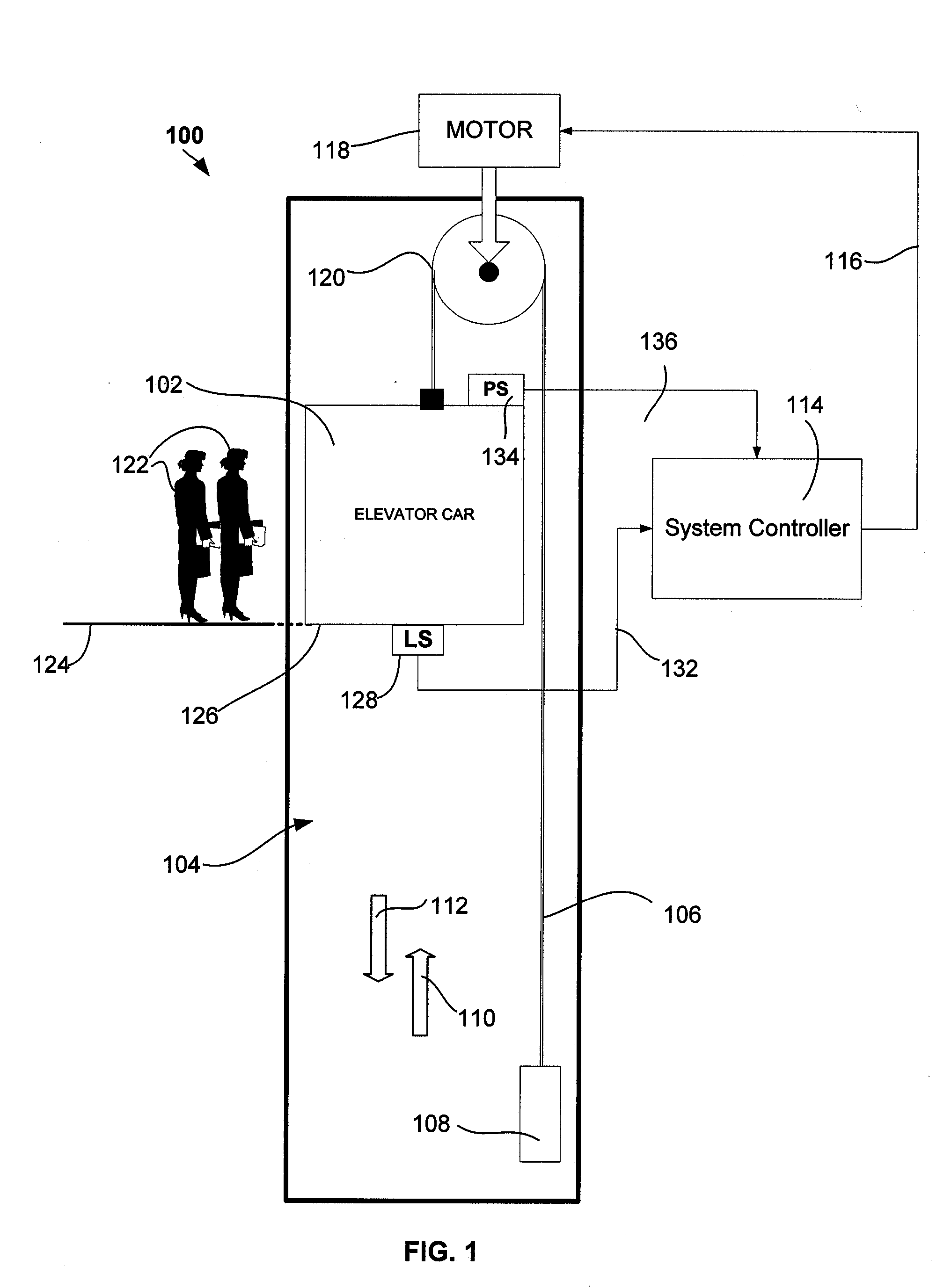
[0014]FIG. 1 illustrates an embodiment of an elevator system 100 according to the present invention. Elevator car 102 is suspended within elevator shaft 104 by means of tension members, such as elevator cable system 106. One end of the cable system 106 is coupled to elevator car 102, while the other end of cable system 106 is connected to a counter weight 108. The elevator moves vertically in the direction of arrows 110 and 112 under the control of elevator system controller 114. Motion control signals are generated by system controller 114 and transferred over communication link 116 to an elevator motor 118. Motor 118 receives the motion control signals and transfers rotational movement to a sheave 120, which in turn provides a corresponding movement to the cable system 106 and elevator car 102.

[0015] Passengers 122 requesting the elevator service, may initiate a hall call request. The hall call request is processed by controller 114, whereby the elevator car 102 is dispatched to ...


PUM


Abstract

The present invention provides an elevator position compensation system which minimizing the re-leveling of an elevator car in an elevator shaft. The elevator car is suspended in the shaft by an elevator cable system and elevator motor, wherein the elevator position compensation system comprises an elevator load sensor device for determining the weight of the elevator car, and generating a load signal indicative of the determined weight. An elevator position sensor determines the position of the elevator car in the elevator shaft and generates a position signal indicative of the determined elevator car position. An elevator control system receives the load signal and the position signal, which is processed by the control system in order to calculate a change in the cable system length associated with a load change within the elevator car, and wherein the calculated change in the cable system length is compensated by the elevator motor.

Description

BACKGROUND OF THE INVENTION [0001] 1. Field of Invention [0002] The present invention concerns a method and apparatus for improving the leveling requirements of an elevator system. In particular, the invention provides a method and apparatus for reducing the required leveling by predicting the suspended load on the elevator's tension members. [0003] 2. Background of Invention [0004] Accurate leveling between the floor of an elevator car and the landing at which the elevator is located, is an essential requirement for the safe operation of elevators. Specifications and industry standards require that elevators maintain a level difference between the elevator car floor and landing floor of within ⅜″. [0005] Elevators are generally suspended by tension members that stretch and change length. The amount by which the tension members may change in length depends on the suspended load, where the load is the weight of the elevator car, plus the weight of its contents (e.g., one or more pers...

Claims


Application Information

Patent Timeline
IPC IPC(8): B66B1/40B66B1/42
CPCB66B1/40
Inventor BRANT, JOHN S.
Owner THYSSENKRUPP ELEVATOR CAPITAL CORP
Learn More