
Cabinet for chemical delivery with solvent purging and removal

a technology for solvent purging and chemical delivery, applied in the field of process chemical delivery, can solve the problems of low volatility chemicals not being effective, safety problems, and the design of the valve in such systems is not configured to minimize the geometries to be cleaned

Inactive Publication Date: 2005-10-20
VERSUM MATERIALS US LLC
View PDF42 Cites 16 Cited by
  • Summary
  • Abstract
  • Description
  • Claims
  • Application Information

AI Technical Summary

Benefits of technology

The present invention is a process and apparatus for storing and delivering a low vapor pressure process chemical to a semiconductor fabrication process tool. The improvement includes steps of receiving and storing residual process chemical from a manifold and solvent used to remove the process chemical by evaporating the solvent. The process includes heating the manifold and the apparatus includes a bulk container, process container, manifolds, solvent container, and a controller for controlling the flow of process chemical and solvent. The apparatus also includes a heater for the bulk container, process container, manifolds, and solvent container. The technical effects include improved storage and delivery of process chemicals with reduced solvent consumption and improved process efficiency.

Problems solved by technology

Both vacuum draw and inert gas purge are successful in quickly removing high volatility chemicals, but are not effective with low volatility chemicals.
Safety is a problem when extracting highly toxic materials.
In addition, the design of the valves in such systems are not configured to minimize the geometries to be cleaned.
These prior art systems require large solvent volumes, excessive cleaning times and complex operations.

Method used


Image

  • Cabinet for chemical delivery with solvent purging and removal
  • Cabinet for chemical delivery with solvent purging and removal
  • Cabinet for chemical delivery with solvent purging and removal

Examples


Embodiment Construction

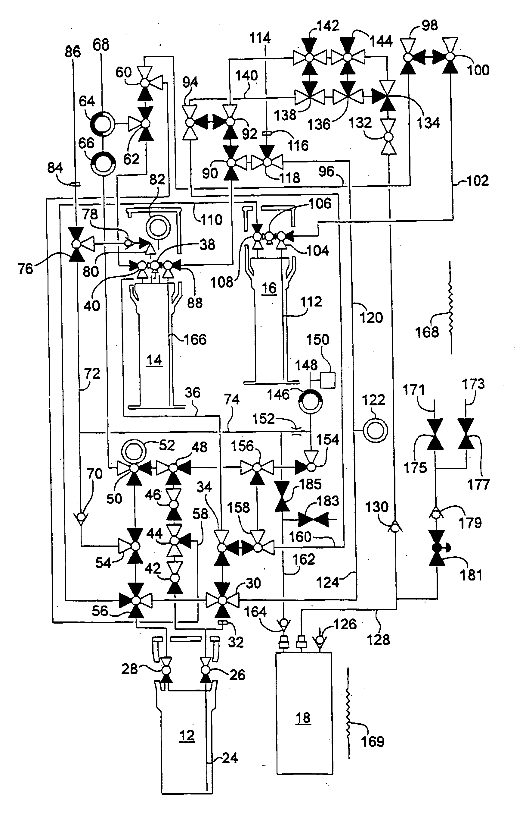
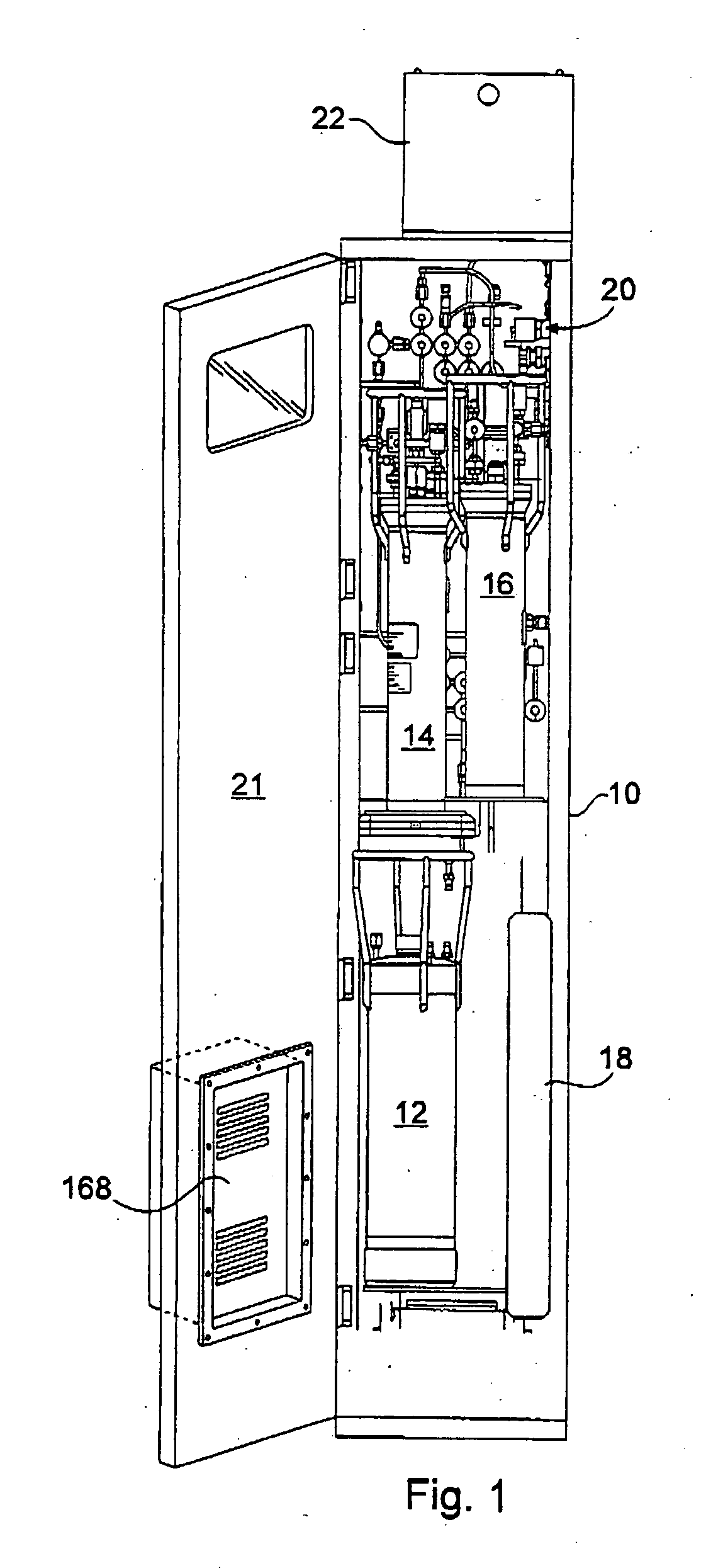
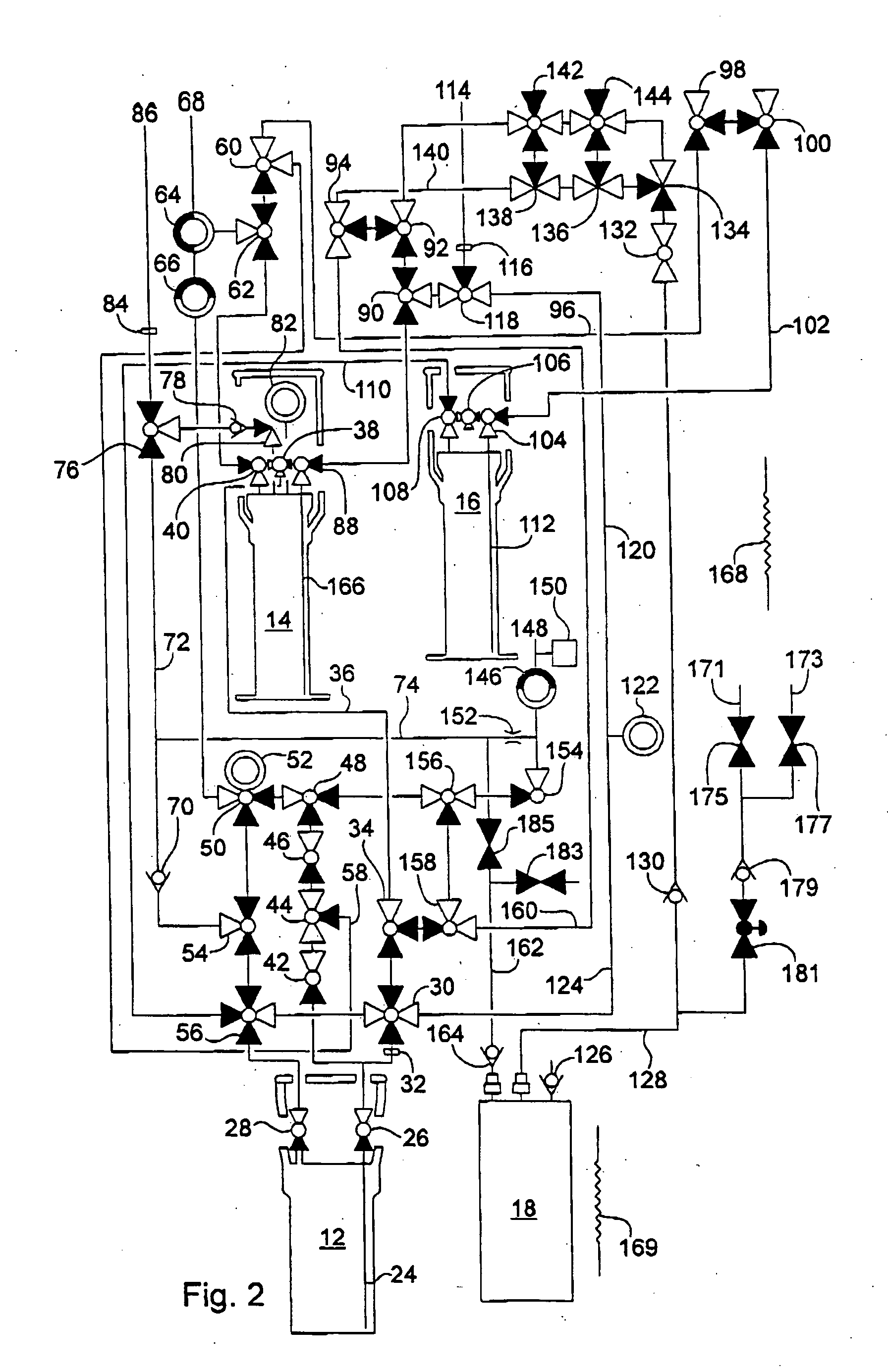
[0043] The present invention is designed to provide one or more liquid chemical precursors to a process tool designed for manufacturing semiconductors, and to allow said precursors to be easily and efficiently cleaned from key areas of piping to permit rapid replacement of process reservoirs, ampoules, degassers, valves and other associated components in the delivery system. These replacements may be required as a result of regular preventive maintenance routines, or they may be required due to a particular component failure or other need to modify or upgrade the system. The apparatus consists of a cabinet for the storage of bulk containers of chemicals, which can range from 1 liter to over 200 liters, depending on the applications. This cabinet may contain one or a plurality of reservoirs connected together through several means.

[0044] In one embodiment, the vessels may be used to feed from one vessel to the next in a daisy chain fashion. In another embodiment the vessels may be h...


PUM

PropertyMeasurementUnit
volumeaaaaaaaaaa
volumeaaaaaaaaaa
pressuresaaaaaaaaaa

Abstract

The present invention is an apparatus and process for storing and delivering a low vapor pressure process chemical to a process tool for semiconductor fabrication, comprising: a) a bulk container for storing the process chemical; b) a process container for delivering the process chemical to the process tool; c) a first manifold for delivering process chemical from the bulk container to the process container; d) a solvent container containing a quantity of solvent, e) a second manifold for delivering the process chemical from the process container to a process tool; f) a solvent recovery container for containing used solvent and removed process chemical, and, g) a solvent evaporator to differentially remove solvent from process chemical in the solvent recovery container by entrainment in a carrier gas, vacuum removal, heating or combinations thereof. The containers can be baffled on their inert gas inlets. The cabinet can be heated.

Description

CROSS REFERENCE TO RELATED APPLICATIONS [0001] The present application is a continuation-in-part of U.S. Ser. No. 10 / 046,614 filed Jan. 14, 2002.BACKGROUND OF THE INVENTION [0002] The Present Invention is directed to the field of process chemical delivery in the electronics industry and other applications requiring high purity chemical delivery. More specifically, the present invention is directed to apparatus and processes for the cleaning of process chemical delivery lines, containers and associated apparatus, particularly during changeout of process chemical or process chemical containers in such process chemical delivery lines. [0003] Evacuation and gas purge of process chemical lines has been used to remove residual chemicals from delivery lines. Both vacuum draw and inert gas purge are successful in quickly removing high volatility chemicals, but are not effective with low volatility chemicals. Safety is a problem when extracting highly toxic materials. [0004] Use of solvents ...

Claims


Application Information

Patent Timeline
Patent Type & Authority Applications(United States)
IPC IPC(8): B67D7/02H01L21/205F17C13/04
CPCB67D7/0272F17C2270/0545C23C16/45561F17C13/04F17C2227/044F17C2270/0518F17C2203/0329F17C2203/0643F17C2205/0146F17C2205/0326F17C2205/0329F17C2205/0335F17C2205/0341F17C2223/047F17C2227/0304F17C2250/032F17C2250/036F17C2250/0413F17C2250/0417F17C2250/0434F17C2250/0491F17C2250/0495F17C2260/013F17C2260/015F17C2260/016F17C2265/017C23C16/448Y10T137/3127Y10T137/4259Y10T137/0419Y10T137/87877Y10T137/0424Y10T137/87893Y10T137/6606B08B7/04
Inventor BIRTCHER, CHARLES MICHAELMARTINEZ, MARTIN CASTANEDASTEIDL, THOMAS ANDREWVIVANCO, GILSILVA, DAVID JAMES
Owner VERSUM MATERIALS US LLC
Learn More