
Simple persistence mechanism for server based web applications

a server-based web application and persistence mechanism technology, applied in the field of object-oriented simple persistence mechanism, can solve the problems of deep flawed and unsuitable use of persistence builder and enterprise java bean®, client and server needs, and inefficient efficiency, and achieve the effect of reducing or eliminating the problems associated with persisten

Inactive Publication Date: 2005-10-13
IBM CORP
View PDF23 Cites 14 Cited by
  • Summary
  • Abstract
  • Description
  • Claims
  • Application Information

AI Technical Summary

Benefits of technology

[0023] The present invention provides a simple persistence mechanism that mitigates or eliminates problems associated with the related art persistence mechanisms.

Problems solved by technology

Nonetheless, both Persistence Builder and Enterprise Java Beans® are deeply flawed and unsuitable for use “as is” in a WebSphere environment.
The interface between the client and server needs to be structured to support an extremely inefficient interface (i.e., remote method invocation or RMI) between the client and server.
This severe inefficiency has made Enterprise Java Beans® very unpopular with web developers.
As explained supra, Enterprise Java Beans® do not offer a suitable alternative.
PersistenceBuilder has its own problems, mainly its attempts at transaction management which are totally inadequate for a clustered environment (i.e., the transaction information is held in memory on one server, so once an interaction crosses servers it loses all integrity).
There are also numerous failings in both Persistence Builder and Enterprise Java Beans®.
PersistenceBuilder does not provide a way to add search criteria for a query, and adding search criteria for a query is cumbersome using Enterprise Java Beans®.
However, there are performance penalties in the code that processes these relationships that can outweigh the buildtime convenience and there are runtime headaches.

Method used


Image

  • Simple persistence mechanism for server based web applications
  • Simple persistence mechanism for server based web applications
  • Simple persistence mechanism for server based web applications

Examples


example

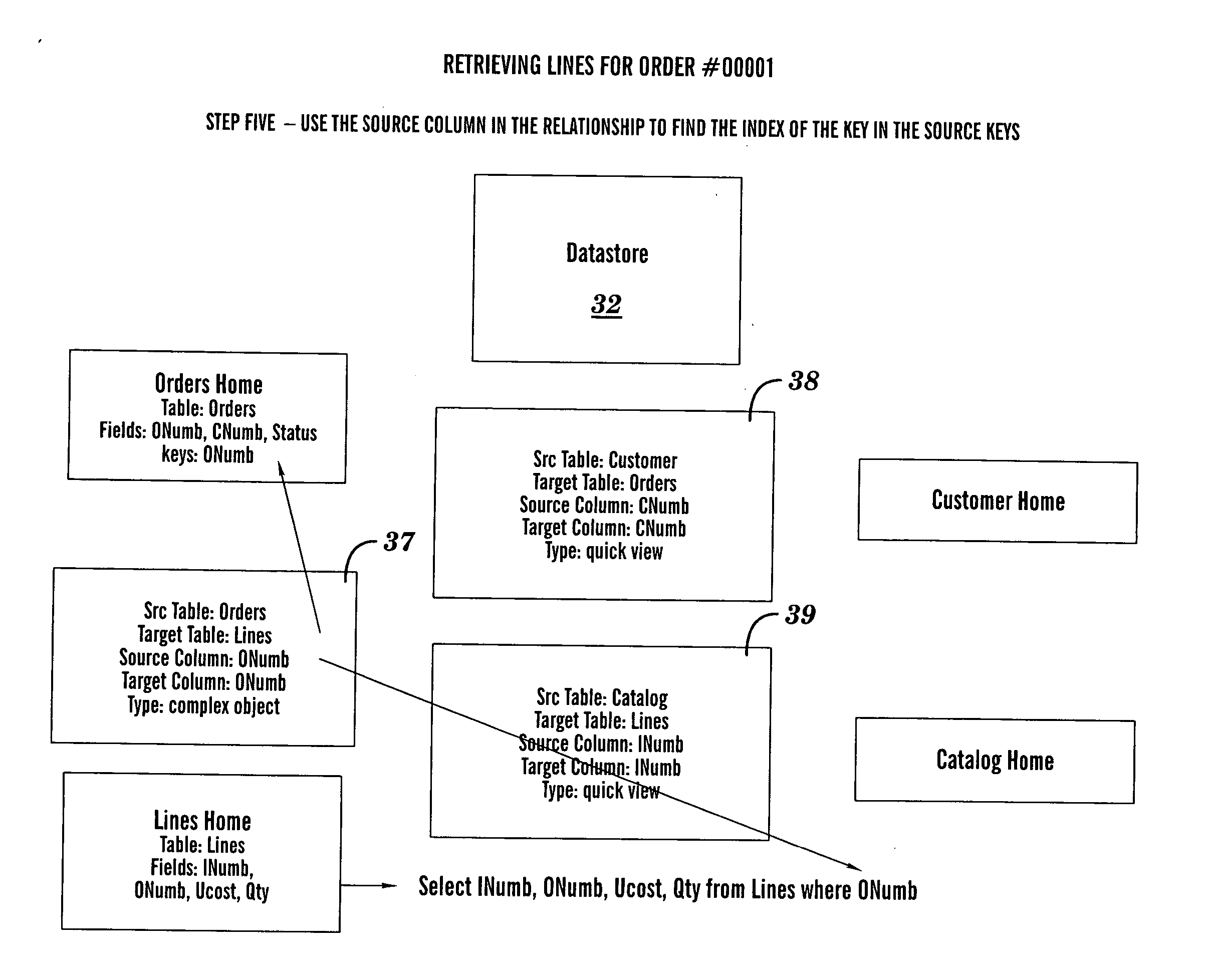
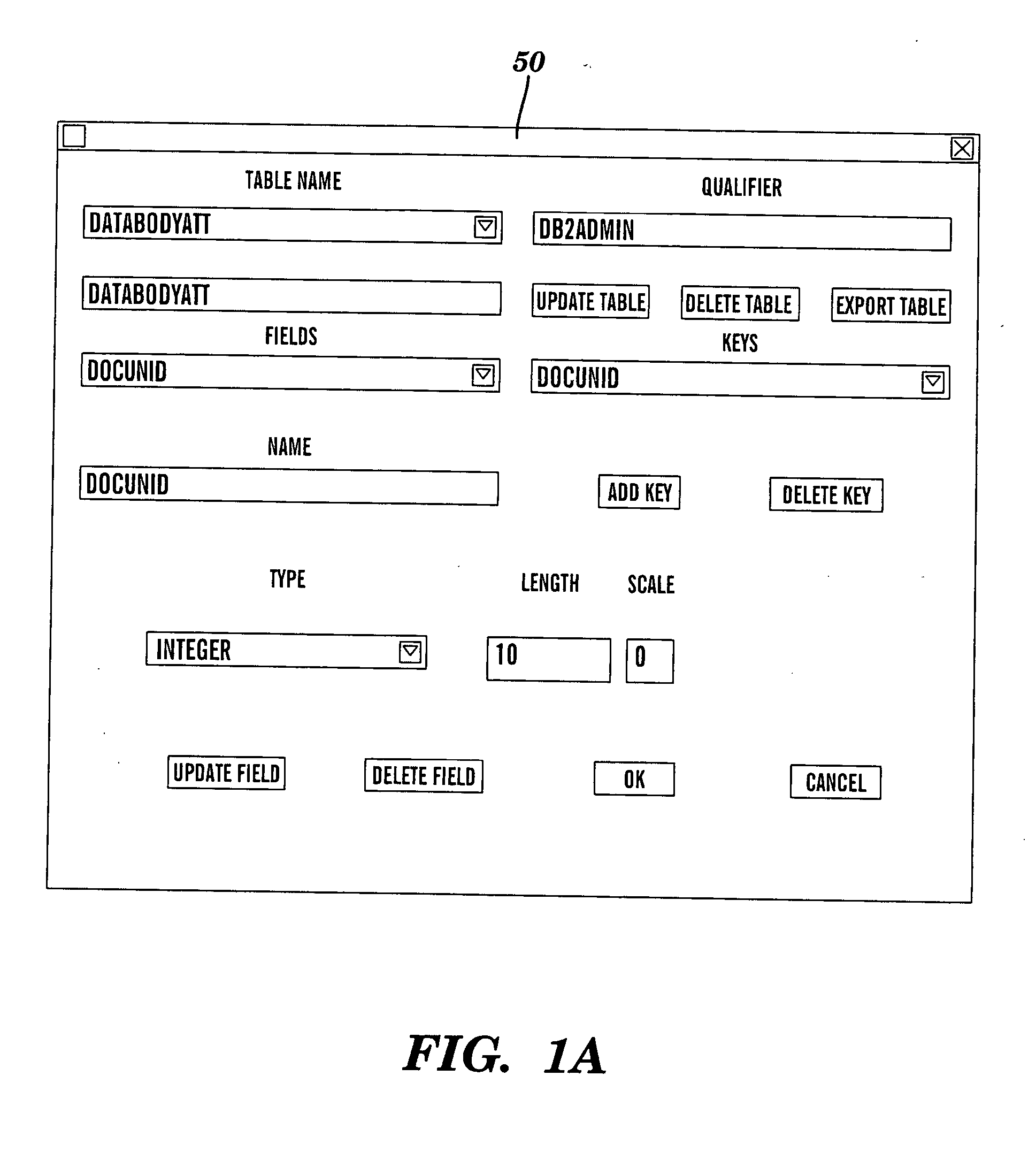
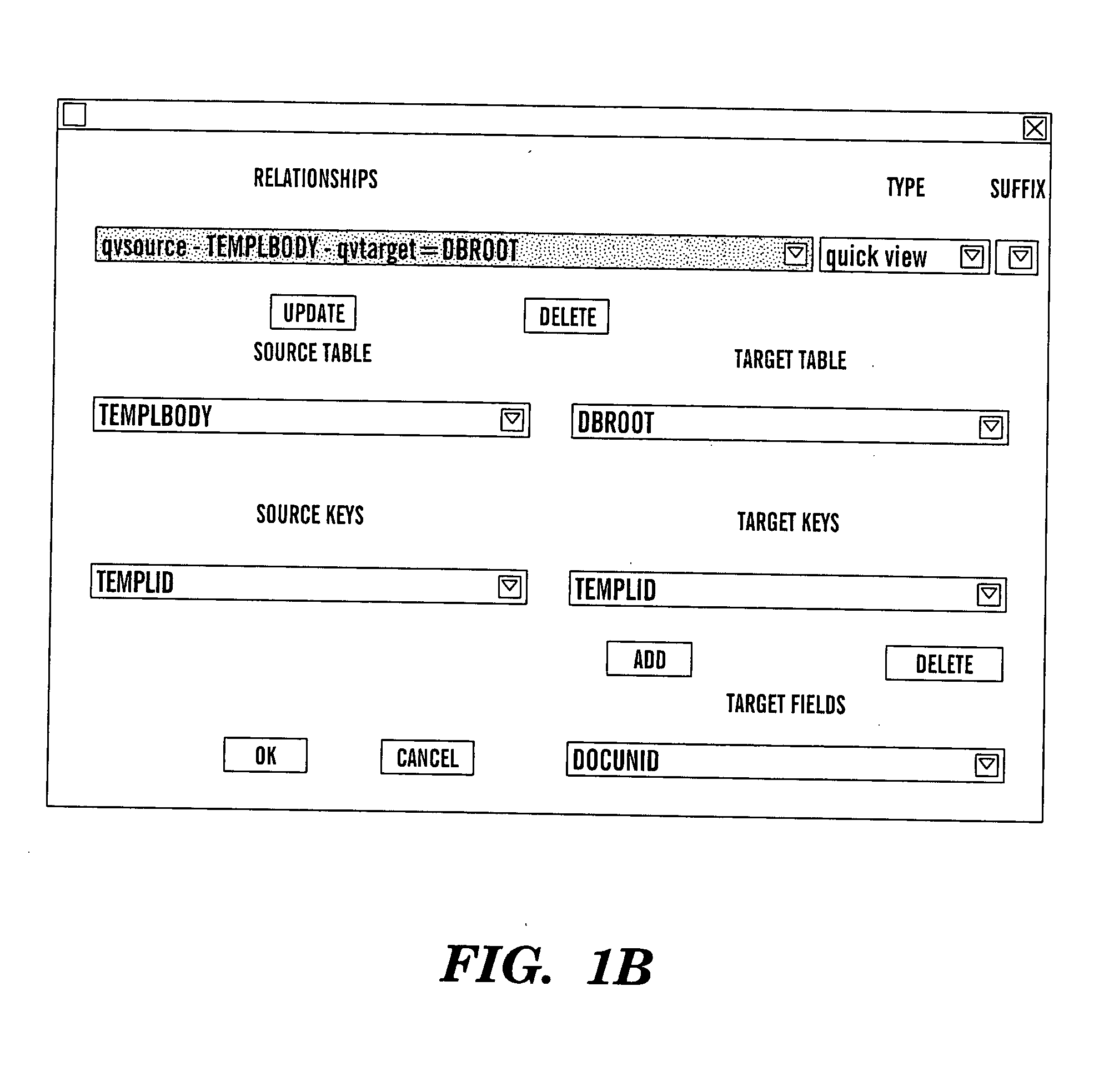
[0159]FIG. 2-21 depict an Example relating to processing orders of items of clothing and clothing accessories from a catalog, in accordance with embodiments of the present invention. FIG. 2-4 show steps for defining the datastore at buildtime, as an illustration of the flow chart of FIG. 22, described supra. FIGS. 5-8 depict illustrative database tables, with columns and rows, for this Example. FIGS. 9-17 depict sequential steps relating to a runtime process of retrieving lines for an order for this Example buildtime, as an illustration of the flow chart of FIG. 23, described supra. FIGS. 18-21 sequential steps relating to a runtine process of retrieving a list of orders for this Example buildtime, as another illustration of the flow chart of FIG. 23, described supra.

[0160]FIG. 2 depicts step one at buildtime, namely exporting schema (i.e., table attributes or metadata) of database tables Orders, Lines, Customer, and Catalog tables from a database 30 to a datastore 32. The Orders, ...


PUM


Abstract

An object oriented method and computer system for implementing a persistence mechanism. The persistence mechanism is adapted to effectuate data transfer between a software application and a relational database. The method identifies homes and relationships. Each identified home includes attributes of a table of the database. Each identified relationship has attributes describing a foreign key interaction between two homes of the identified homes. A provided home class is adapted to be instantiated to any of the identified homes. A query to transfer data between the application and the database is generated such that a first home of the identified homes is processed. The first home includes attributes of a first table of the database. The processing of the first home includes an instantiation of the home class to an instance of the first home by setting attributes of the first home.

Description

CROSS REFERENCE TO COPENDING APPLICATIONS [0001] The disclosure of this application is related to the disclosures of the following copending applications: [0002]“Complex Data Navigation, Manipulation and Presentation Support for Visualage Java,” Ser. No. 09 / 615,976, filed Jul. 14, 2000; and [0003]“Web and Lotus Notes Adapter Layers,” Ser. No. 10 / 157,262, filed May 29, 2002. The two above-identified copending applications are hereby incorporated herein by reference in their entirety.BACKGROUND OF THE INVENTION [0004] 1. Technical Field [0005] The present invention relates to an object oriented simple persistence mechanism for effectuating data transfer between a software application and a relational database. [0006] 2. Related Art [0007] Object oriented programming systems typically use persistence mechanisms to mediate between Enterprise Java Beans® software applications and relational databases such as DB2®. A persistence mechanism is generic software which functions as an interfac...

Claims


Application Information

Patent Timeline
IPC IPC(8): G06F17/00
CPCG06F17/30595G06F17/30607Y10S707/99944Y10S707/99933Y10S707/99943G06F16/284G06F16/289
Inventor WASON, JAMES R.
Owner IBM CORP
Learn More