[0008] The present invention encompasses light generating devices for illuminating portions of
vascular tissue to enable PDT to be provided. Each embodiment includes one or more light sources configured to be positioned inside a
body cavity or a vascular
system. While the term “light source array” is frequently employed herein, because particularly preferred embodiments, of this invention include multiple light sources arranged in a radial or
linear configuration, it should be understood that a single light source could be employed. Using a plurality of light sources enables larger treatment areas to be illuminated. Light emitting diodes (LEDs) are particularly preferred as light sources, although other types of light sources can be employed, as will be described in detail below. The light source that is used will be selected based on the characteristics of a photoreactive agent in connection with which the apparatus is intended to be used, since light of incorrect wavelengths will not cause the desired reaction by the photoreactive agent.
Light source arrays can include light sources that provide more than one
wavelength or waveband of light. Linear light source arrays are particularly useful to treat elongate portions of tissue.
Light source arrays can also include reflective elements to enhance the transmission of light in a preferred direction. Each embodiment described herein can beneficially include expandable members such as
inflatable balloons to occlude
blood flow (which can interfere with the transmission of light from the light source to the intended
target tissue) and to enable the apparatus to be centered in a
blood vessel.
[0009] In configurations where light is intended to be directed through such expandable members to reach
target tissue, the expandable members are preferably constructed from materials that substantially transmit the required wavelength of light. Bio-compatible polymers having the required optical characteristics are particularly preferred. Where light is directed through such expandable members to reach
target tissue, a fluid used to inflate the expandable members can include additives to enhance the transmission or
diffusion of light. In configurations where an expandable member is disposed
proximate to a light source array, the fluid used to expand the member acts as a
heat sink to absorb heat generated by the light source array. Regularly replacing the fluid within the expandable member will enhance the cooling effects.
Positioning aids, such as radio-opaque markers, can be included to enable any of the embodiments described in detail below to be properly positioned with respect to a target area.
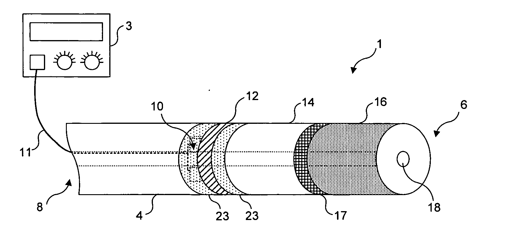
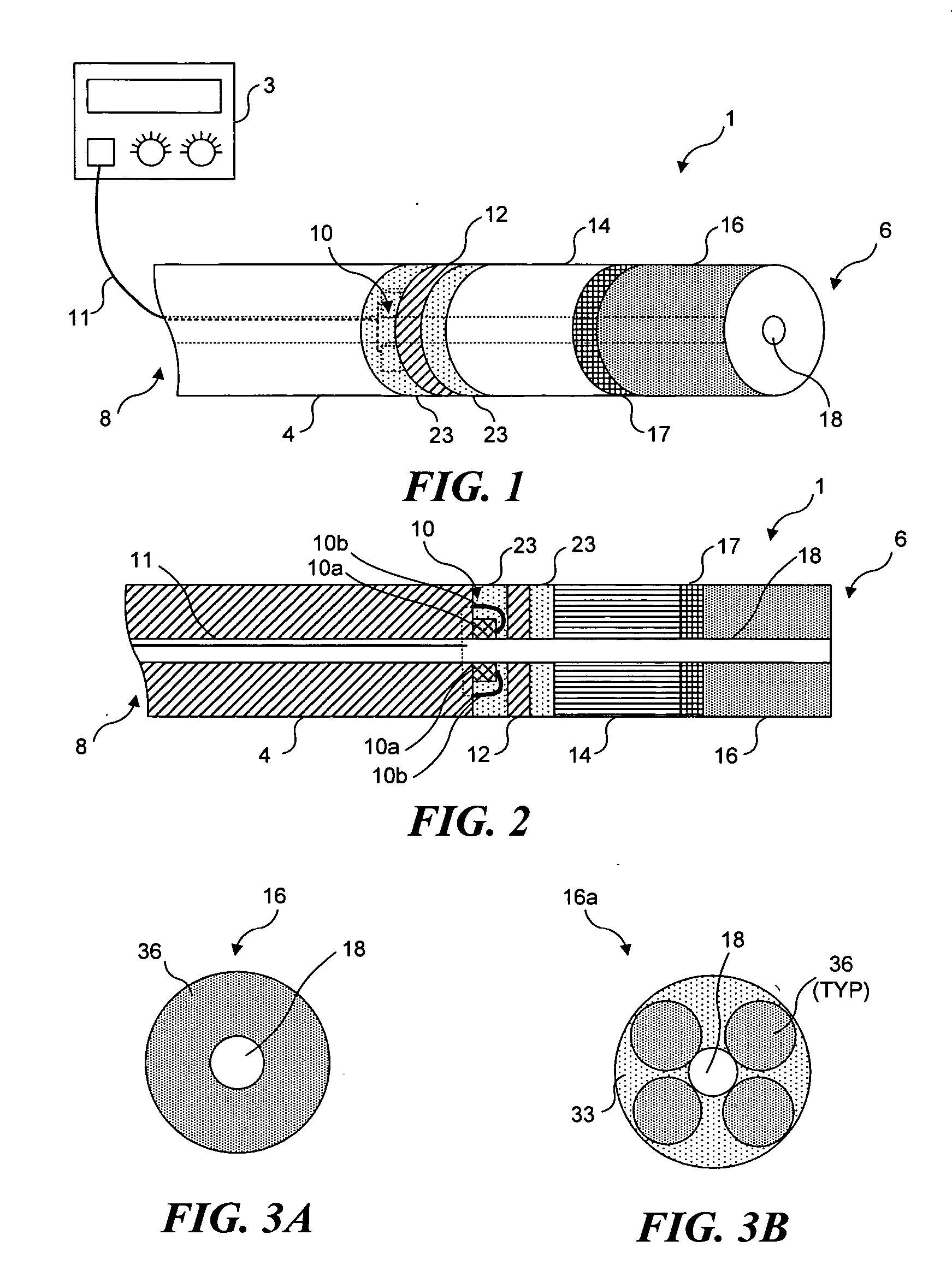
[0010] A first preferred embodiment is configured to emit light from a distal tip of an elongate flexible body. The first preferred embodiment includes an elongate flexible body having a distal end and a proximal end, with at least one lumen extending therebetween. A
distal portion of the first embodiment includes a light source array and a light diffusing element configured to disperse light from the light source array outward from the distal tip of the apparatus. An electrical lead extends from the light source array to at least a proximal end of the elongate, flexible body, so that the electrical lead can be coupled to an external power source to energize the light source array. A focusing lens and one or more optical fibers are preferably disposed between the light source array and the light diffusing element. Incorporating a lumen extending through the apparatus enables the apparatus to be advanced to a desired position using a guidewire. A radio-opaque material can be included immediately adjacent to the light diffusing element to facilitate the proper positioning of the light diffusing element relative to a target area. A radially oriented light source array is used in such a first preferred embodiment.
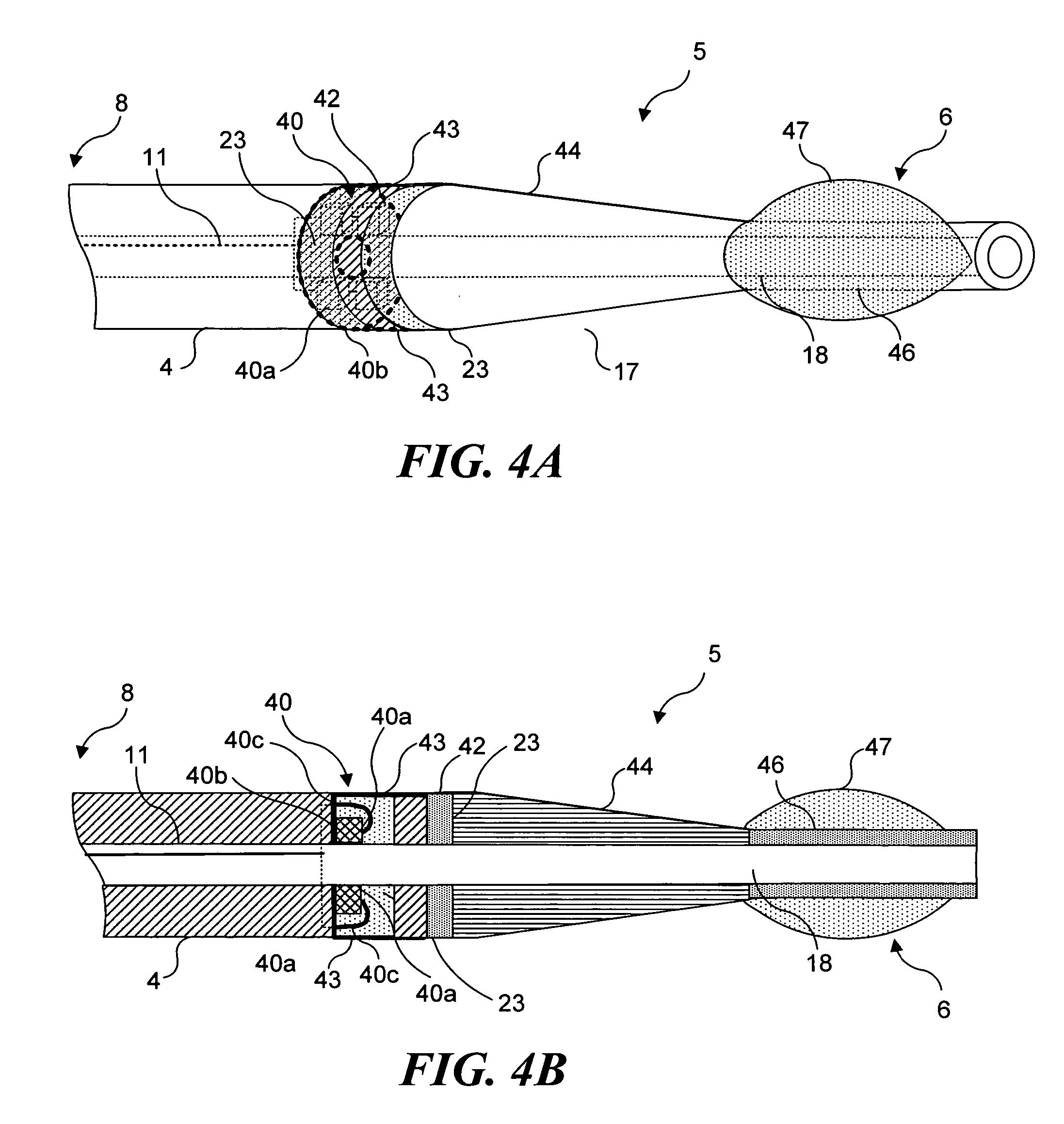
[0013] Preferably, this embodiment includes an expandable member disposed to substantially encompass the light source array. Accordingly, the elongate flexible body includes an inflation lumen to enable the expandable member to be inflated. Preferably, each end of the light source array is marked with a radio-opaque tag (or some other type of identifier) so that the light source array can be properly positioned adjacent to target tissue. The length of the
linear array is only limited by the length of the expandable member. If the
linear array is made longer than the expandable member, light emitted from that portion of the
linear array extending beyond the expandable member will be blocked by blood, and is not likely to reach the target tissue. As described below, the use of a plurality of expandable members enables longer linear light sources to be used.
[0014] Use of a linear light source array in an apparatus configured in accord with the present invention requires that the array be sufficiently flexible to enable the resulting device to be advanced through a vascular
system. LEDs are sufficiently small and compact, so that when LEDs are mounted to a flexible conductive substrate, a flexible light source array is achieved that meets this requirement. The flexibility of the linear light source array can be further enhanced by including
strain relief elements in the light source array. Also, including a plurality of folds or bends in the flexible conductive substrate will further enhance the flexibility of the substrate. The
polymer employed to encapsulate the LEDs and conductive substrate is preferably selected to be both optically transparent to the required wavelength of the light used, and sufficiently flexible.
[0022] The embodiments described above are used with a photoreactive agent that is introduced into the target area prior to the apparatus being introduced into the
blood vessel. However, it will be understood that if desired, the apparatus can optionally include a lumen for delivering a photoreactive agent into the target area. The resulting embodiments are likely to be particularly beneficial where uptake of the photoreactive agent into the target tissues is relatively rapid, so that the apparatus does not need to remain in the blood vessel for an extended period of time while the photoreactive agent is distributed into and absorbed by the target tissue.


