Spindle motor

Inactive Publication Date: 2005-10-06
MINEBEA CO LTD
View PDF2 Cites 27 Cited by
  • Summary
  • Abstract
  • Description
  • Claims
  • Application Information

AI Technical Summary

Benefits of technology

[0007] In order to achieve the object, according to a 
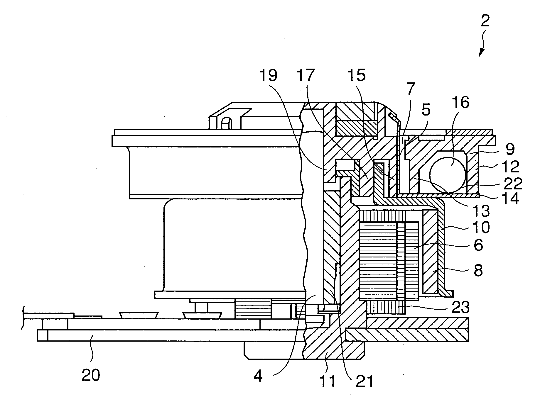
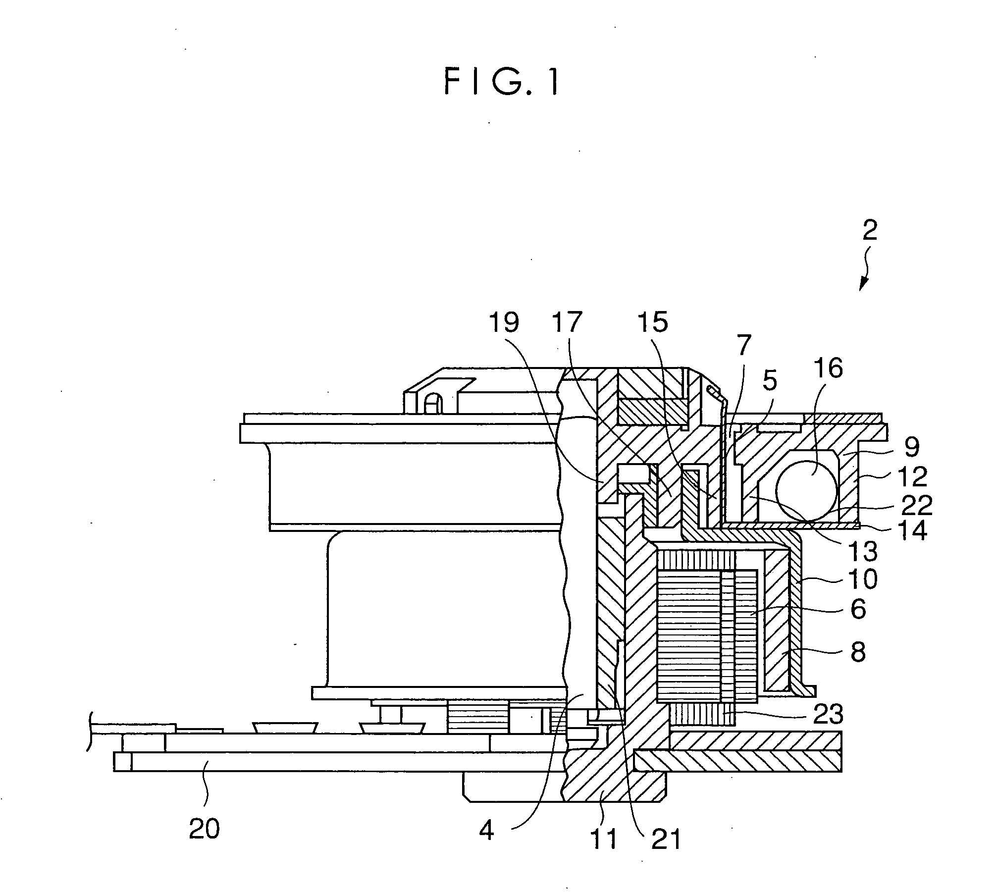
fist aspect of the present invention, there is provided a spindle motor comprising: a turntable for receiving a recording disk; a holder plate disposed under the turntable; and a self-balancing mechanism including an enclosed space which is defined by the turntable and the holder plate, shaped like an annular ring, and which has a plurality of balls movably disposed thereinside, wherein the turntable has a plurality of openings pierced in its thickness direction and arrayed in its circumferential direction, and wherein the holder plate defines a circular opening at its center and has a plurality of claw-shaped aligning members which are punched out so as to remain in an area corresponding to the circular opening, bent up at an inner circumference of the circular opening perpendicularly to the holder plate so as to be inserted respectively through the openings of the turntable, and which have their tip portions protruding from a top face of the turntable, thereby allowing the disk mounted on the turntable to be a centrally aligned. With this structure, the bottom plate of the self-balancing mechanism, that is the holder plate, is formed integrally with the claw-shaped aligning members thereby decreasing the numbers of components and assembling processes as well, and at the same time the length of the claw-shaped aligning member is increased for the height of the self-balancing mechanism thereby making it easier to optimize the spring constant of the aligning member.
[0008] According to a second aspect of the present invention, in the spindle motor of the first aspect, the holder plate may be made of a steel plate, and each of the claw-shaped aligning members may be bent toward a center of the turntable at its tip portion. Consecuently, the claw-shaped aligning members improve readily in durability, and the disk is prevented from getting scratched when mounted on or dismounded from the turntable.
[0011] According to a fifth aspect of the present invention, in the spindle motor of any one of the first to fourth aspects, the inner circumference of the holder plate may be engaged with the outer circumference of a partition formed on a face of the turntable opposite to the top face for receiving the disk. Consecuently, the aligning members are precisely positioned with respect to the center of the turntable thereby precisely getting the disk centered on the turntable.
[0012] Thus, the spindle motor according to the present invention includes a self-balancing mechanism, in which the holder plate made of steel and adapted to cover the bottom face of the turntable is provided with a plurality of claw-shaped aligning members which go through respective openings of the turntable so as to have their tip portions protrude from the top face of the turntable thereby providing a function to centrally align the disk. Consecuently, the disk can be duly centered on the turntable without increasing the numbers of components and also with reduced number of assembling processes.
[0013] Further, the claw-shaped aligning members of the holder plate are engaged with the circular positioning partition of the turntable, and therefore can be constantly positioned at a predetermined place. Also, the claw-shaped aligning members are allowed to be dimensioned larger than conventionally, and therefore can be sufficiently elastic.
[0014] Still further, since the claw-shaped aligning members are curved with a predetermined curvature, the disk can be loaded and unloaded easily, and at the same time can be free from scratches thereby securely fixing the disk and achieving a high endurance.

Problems solved by technology

When a spindle motor is rotated at a high speed in an optical or any other type disk drive with a recording disk unbalancedly loaded, the disk drive vibrates, which may possibly trigger errors in recording in and reproducing from the disk, and which may lead to vibrating also peripheral equipments resulting in malfunction.
Also, it may happen that a disk is not centrally aligned on a turntable due to the variation in its inner diameter dimension.
Since the aforementioned aligning members must be durable, specifically abrasion-resistant to survive frequent loading and unloading of disks while the turntable including the center guide must be precisely dimensioned, it is difficult to satisfy the different requirements of the both components if they are formed using the same resin material.
On the other hand, if the both components are formed using different resin materials, the numbers of materials, components, and also processes are increased thus pushing up production cost.

Method used


Image

  • Spindle motor
  • Spindle motor
  • Spindle motor

Examples


Embodiment Construction

[0021] A preferred embodiment of the present invention will be described with reference to the accompanying drawings.

[0022] Referring to FIG. 1, a spindle motor 2 according to the embodiment of the present invention generally comprises a motor assembly 31 composed of a rotary shaft 4, a stator 6, a rotor magnet 8, a rotor yoke 10, and a housing 11, further comprises a turntable 12, and a holder plate 14, and is attached to a base plate 20.

[0023] The rotor magnet 8 is a hollow-cylindrical permanent magnet, and fixed to the inner circumference of the rotor yoke 10, which, together with the turntable 12, is fixedly attached to the rotary shaft 4.

[0024] The rotary shaft 4 is rotatably held by a bearing 21 disposed inside the housing 11 attached to the base plate 20.

[0025] The stator 6 has coils 23 wound therearound, is fixed to the housing 11, and faces the inner circumferential surface of the rotor magnet 8 with a slight air gap therebetween. The rotor yoke 10 is made of a steel pl...


PUM


Abstract

A spindle motor, in which the number of parts is kept from increasing and the number of assembling processes is reduced, and which has mechanisms for self-balancing and centrally aligning a disk, comprises a motor assembly (31) for rotating a disk (30) as a recording medium, a turntable (12) for mounting the disk (30), and a holder plate (14) disposed under the turntable (12). The mechanism for self-balancing is structured such that a plurality of steel balls (16) are disposed within an annular space (22) defined by the turntable (12) and the holder plate (14), and the mechanism for centrally aligning the disk (30) is constituted by a plurality of claw-shaped aligning members (5) formed at the inner circumference of the holder plate (14).

Description

FIELD OF THE INVENTION [0001] The present invention relates to a spindle motor which is provided with mechanisms for self-balancing and centrally aligning a recording disk. BACKGROUND OF THE INVENTION [0002] When a spindle motor is rotated at a high speed in an optical or any other type disk drive with a recording disk unbalancedly loaded, the disk drive vibrates, which may possibly trigger errors in recording in and reproducing from the disk, and which may lead to vibrating also peripheral equipments resulting in malfunction. [0003] In order to deal with the problem of the disk drive vibrating due to the disk loaded with its gravity point positioned off a rotational axis, a spindle motor disclosed in Japanese Patent Application Laid-Open No. 2000-308306 is equipped with a self-balancing mechanism, which comprises an enclosed space having an annular ring shape, and balls adapted to freely move in the enclosed space, and which works such that the balls move automatically in the direc...

Claims


Application Information

Patent Timeline
IPC IPC(8): G11B17/028G11B19/20H02K7/04H02K15/16H02K21/22
CPCG11B17/0282G11B19/2009G11B19/2027H02K7/04H02K15/165G11B19/20G11B17/028H02K15/16
Inventor MATSUSHITA, KUNITAKEYAMAWAKI, TAKAYUKISUZUKI, KATSUTOSHIINAGAKI, MASAAKI
Owner MINEBEA CO LTD
Why Eureka
Try Eureka