
Suture anchor with apertures at tip

a technology of suture anchor and distal tip, which is applied in the field of suture anchors with apertures at the distal tip, can solve the problems of suture being detached from the anchor prematurely, unraveling or pulling through the distal portion of the passageway, and weakening the drive head

Active Publication Date: 2005-10-06
ARTHREX
View PDF9 Cites 253 Cited by
  • Summary
  • Abstract
  • Description
  • Claims
  • Application Information

AI Technical Summary

Benefits of technology

[0013] The present invention provides a suture anchor which securely affixes sutures to the anchor without subjecting the sutures to abrasion by the surrounding bone or subjecting the tissue to be secured with the suture anchor to be abraded by the sutures. Moreover, the suture anchor according to the present invention can be installed without countersinking.
[0015] Suture strands can be inserted into the suture anchor through the apertures, and when the ends of the sutures are pulled as far as possible out the proximal end of the suture anchor, the portion of the sutures seated in the grooves are thereby protected from abrasion during installation of the suture anchor.

Problems solved by technology

If the knot is not tied securely or if the knot is not made large enough, there is a risk that the knot will unravel or be pulled through the distal portion of the passageway.
Since the eyelet is formed as part of the drive head, however, combining these two functions in one structure often tends to weaken the drive head.
Problems can arise if the structure for attaching the suture fails, allowing the suture to become detached from the anchor.
For example, if the suture anchor is biodegradable, the eyelet can degrade rapidly, causing the suture to become detached from the anchor prematurely.
As a result, suture attached to the eyelet is vulnerable to abrasion by the bony rim of the countersunk hole into which the suture anchor is installed.

Method used


Image

  • Suture anchor with apertures at tip
  • Suture anchor with apertures at tip
  • Suture anchor with apertures at tip

Examples


Embodiment Construction

[0024] In the following detailed description, reference is made to various specific embodiments in which the invention may be practiced. These embodiments are described with sufficient detail to enable those skilled in the art to practice the invention, and it is to be understood that other embodiments may be employed, and that structural and logical changes may be made without departing from the spirit or scope of the present invention.

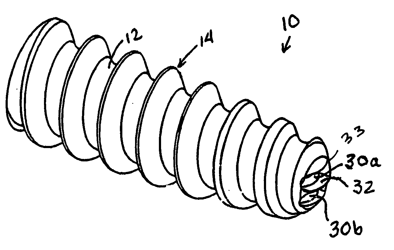
[0025] Referring first to FIGS. 1 and 2, an exemplary embodiment of the suture anchor according to the present invention is identified generally by reference numeral 10. Suture anchor 10 includes a body 12 formed generally in the shape of a slightly tapered cylinder and having a blunt or slightly rounded distal end. In an exemplary embodiment, suture anchor 10 is provided with about eight flights of thread 14 wrapping around body 12, with the angle of the proximal surface 16 of each thread being approximately between one-third and one-fourth the ang...


PUM


Abstract

A suture anchor includes a threaded anchor body having a bore for receiving a driver, and at least two distal passageways extending from the bore to corresponding apertures at the distal end of the suture anchor. The apertures are provided as pairs with a corresponding groove formed between the apertures of the pair. Suture strands can be inserted into the suture anchor through the apertures, the distal portion of the sutures seated in the grooves between the apertures being protected from abrasion during installation of the suture anchor.

Description

[0001] This application claims the benefit of U.S. Provisional Application Ser. No. 60 / 559,426, filed Apr. 6, 2004.BACKGROUND OF THE INVENTION [0002] 1. Field of the Invention [0003] The present invention relates to an apparatus for anchoring surgical suture to bone. More specifically, the present invention relates to a suture anchor having apertures at the distal tip thereof for anchoring sutures in the cortical bone during arthroscopic surgery. [0004] 2. Description of the Related Art [0005] When soft tissue tears away from bone, re-attachment becomes necessary. Various devices, including sutures, screws, staples, wedges, and plugs have been used in the prior art to secure soft tissue to bone. [0006] Recently, various types of threaded suture anchors have been developed for this purpose. Some threaded suture anchors are designed to be inserted into a pre-drilled hole. Other suture anchors are self-tapping. [0007] U.S. Pat. No. 5,156,616, for example, discloses a suture anchor whic...

Claims


Application Information

Patent Timeline
IPC IPC(8): A61B17/04A61F2/30
CPCA61B17/0401A61B2017/0409A61B2017/0414A61B2017/044A61B2017/0458
Inventor DREYFUSS, PETER J.BENAVITZ, WILLIAM C.
Owner ARTHREX
Learn More