
Connector for memory card

a technology for connecting devices and memory cards, applied in the direction of coupling device connections, coupling parts engagement/disengagement, instruments, etc., can solve the problems of difficult further downsizing of mobile equipment, the connector itself cannot be downsized, etc., to reduce the number of components, simplify the constitution of the connector, and reduce the effect of slider

Inactive Publication Date: 2005-10-06
MATSUSHITA ELECTRIC WORKS LTD
View PDF7 Cites 29 Cited by
  • Summary
  • Abstract
  • Description
  • Claims
  • Application Information

AI Technical Summary

Benefits of technology

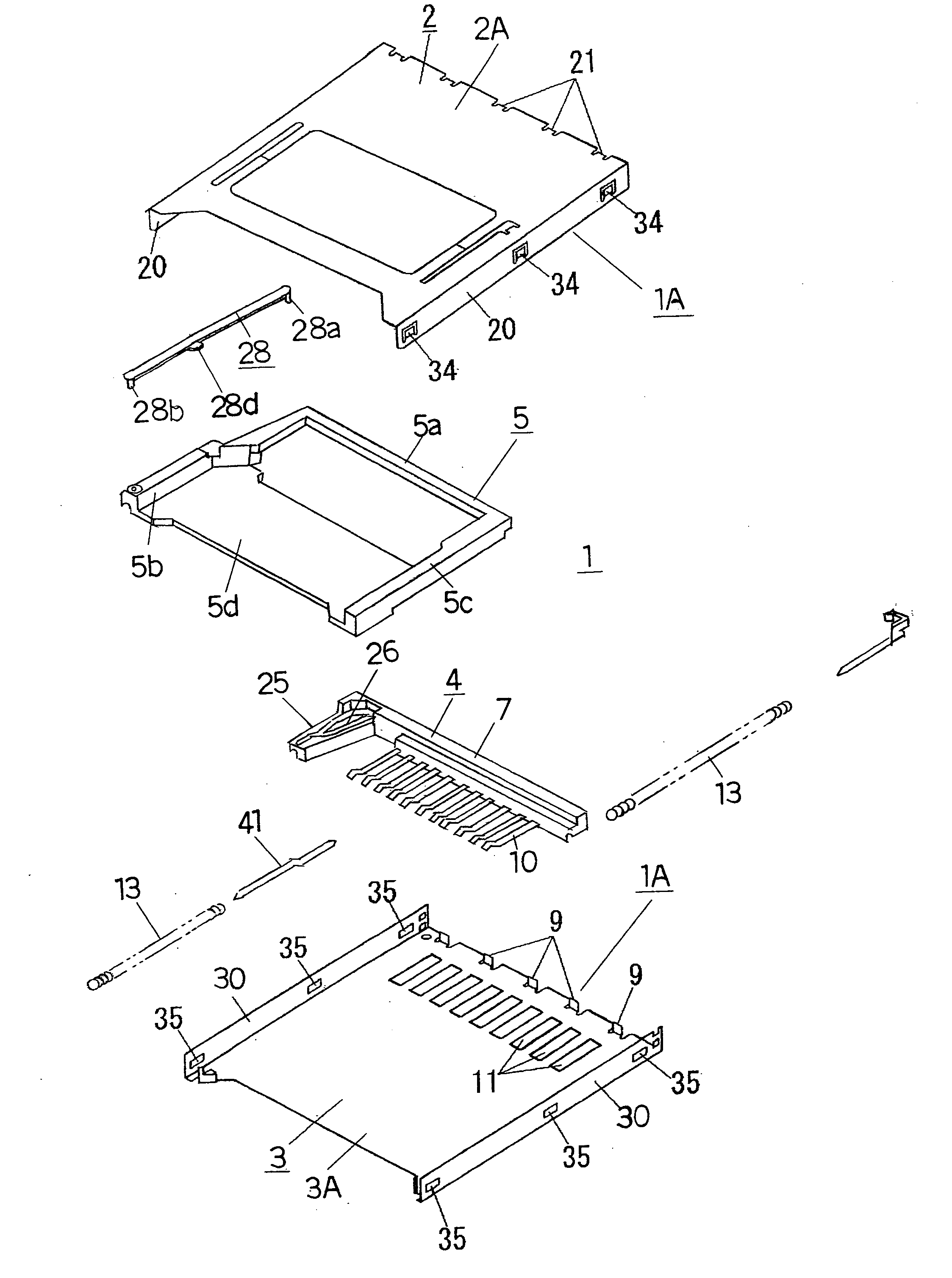
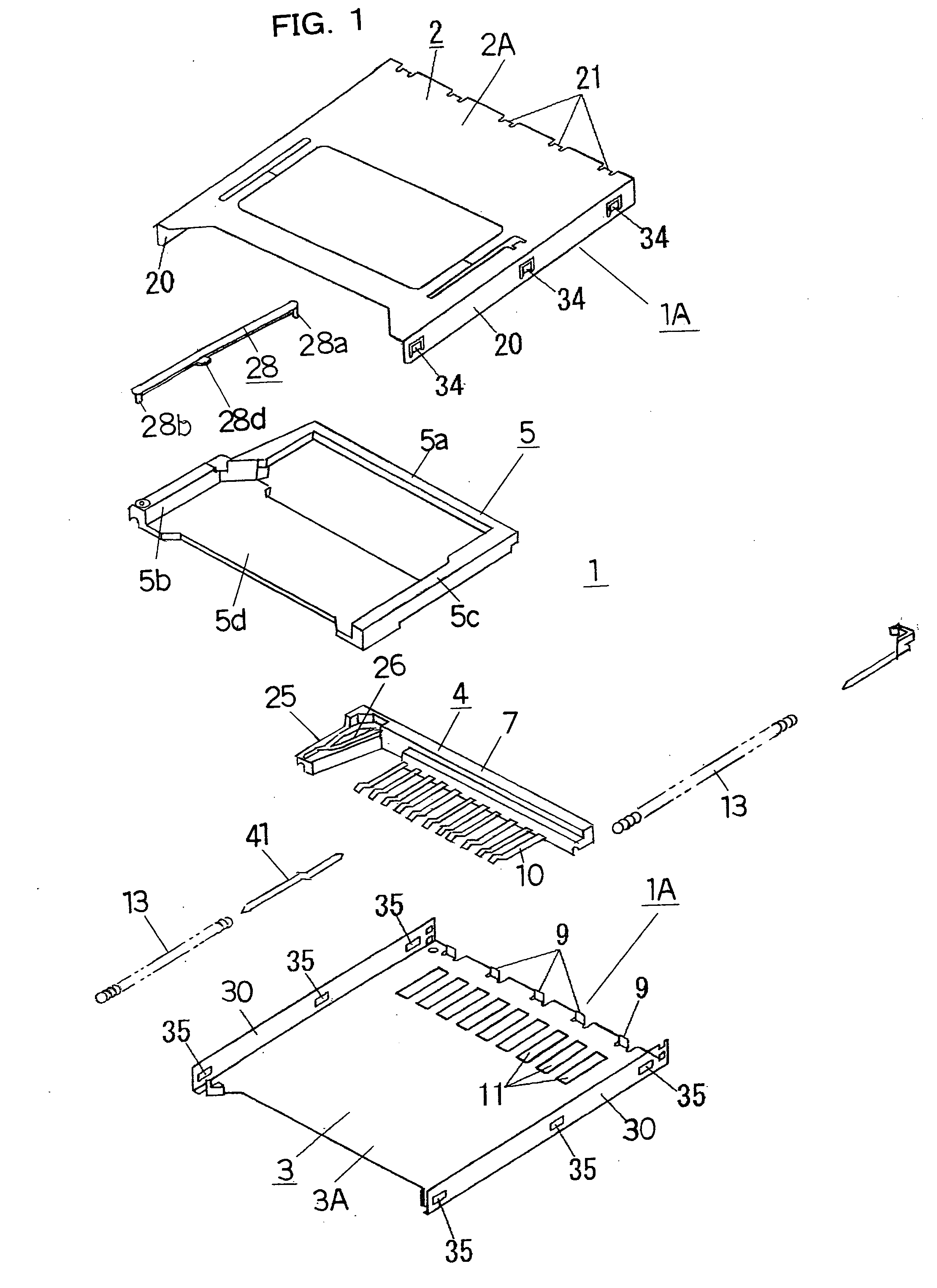
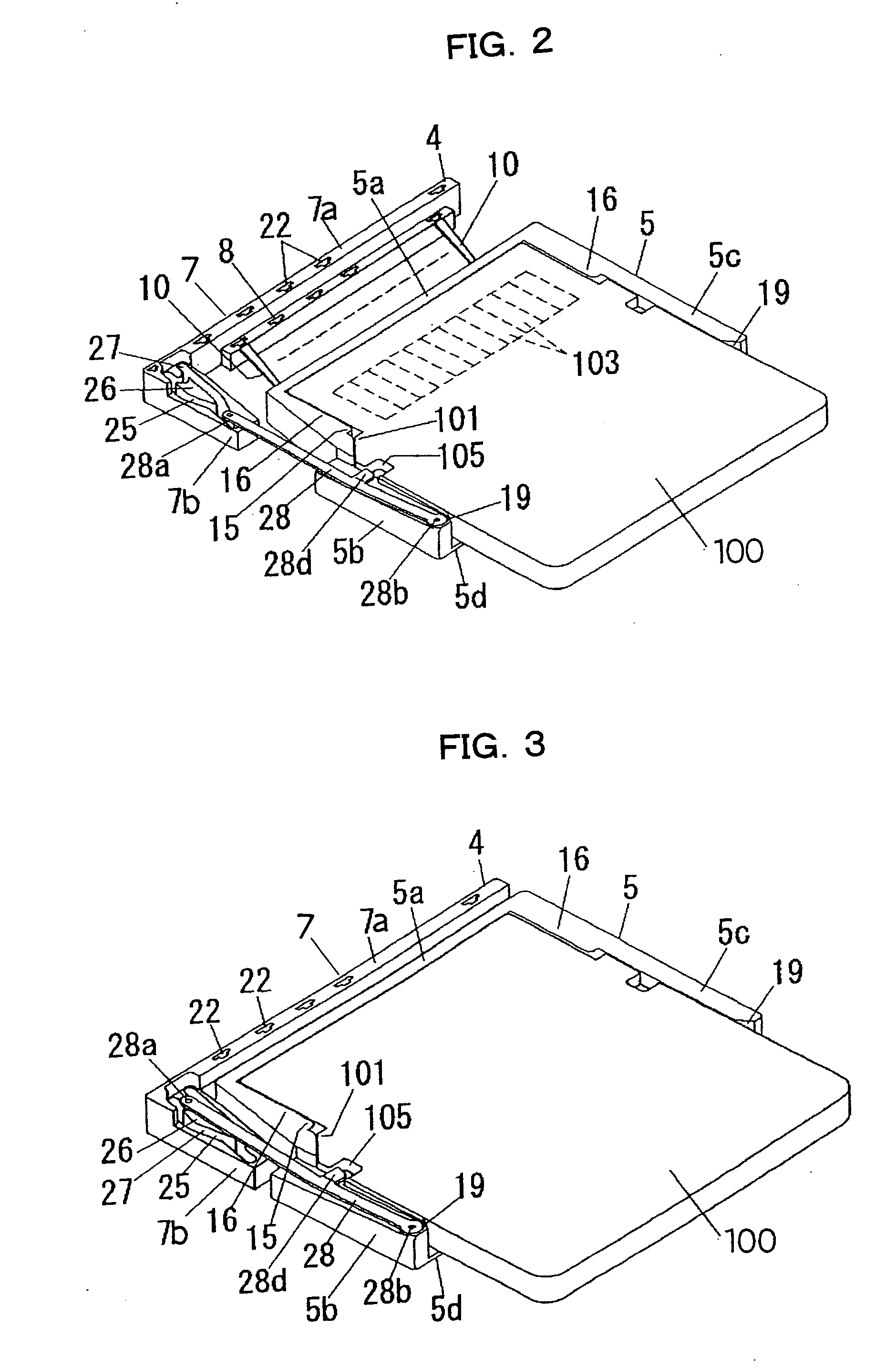
[0014] By such a configuration, since the hart-shaped cam groove unit is provided on the contact block fixed on the housing, it is possible to downsize the slider in comparison with the conventional connector in which the hart-shaped cam groove unit is provided on the slider. Furthermore, since the locking protrusion engaging with the recess used to be locked of the memory card for preventing the dropout is provided on the locking member locking the slider at the predetermined position, it is possible to make the constitution of the connector simple and to downsize the connector 1 (SIC) owing to reduce number of components in comparison with a case that a mechanism for locking the memory card is provided further to the push-on / push-off mechanism, like the conventional connector.

Problems solved by technology

However, when a locking mechanism is provided further to a push-on / push-off mechanism, like the above-mentioned conventional connector for memory card, the connector itself cannot be downsized despite of downsizing of the memory card, so that it is difficult to downsize the mobile equipment furthermore.

Method used


Image

  • Connector for memory card
  • Connector for memory card
  • Connector for memory card

Examples


Embodiment Construction

[0031] A connector for memory card in accordance with an embodiment of the present invention is described. A constitution of a mini-SD card is described with reference to FIGS. 16A to 16E first, as an example of a memory card in this embodiment. It is needless to say that the present invention can be applied to another memory card other than the mini-SD card.

[0032] A memory card 100, which is called mini-SD card downsized from the conventional SD memory (SIC), has a thickness substantially the same as that of the conventional one but an outer shape thereof is one size smaller. As can be seen from the figures, the memory card 100 has substantially a flat rectangular shape, and a cutting portion 101 is provided at a corner of insertion side (front end) thereof. A recess 102 is formed on a bottom face in the insertion side of the memory card 100, and a plurality of (eleven in the case of the mini-SD card) I / O contact terminals 103 is aligned in the recess 102 in parallel with a widthw...


PUM


Abstract

In a connector for memory card used in a mobile equipment, a locking mechanism of a memory card at a card lock position is integrally provided with a push-on / push-off mechanism constituted by a hart-shaped cam and a cam pin, so that the connector can be downsized. A hart-shaped cam groove unit is provided on a contact block fixed on a housing, and an end of a locking member is rotatably borne on a slider which can reciprocally be moved in an inside of the housing. The cam pin is provided on the other end of the locking member, and the cam pin is moved along the hart-shaped cam groove corresponding to reciprocal movement of the slider. Furthermore, a locking protrusion is provided on the locking member for protruding toward the memory card. The hart-shaped cam groove is formed in a manner so that not only the movement of the slider is locked but also the locking protrusion engages with a recess used to be locked provided on the memory card at a card lock position.

Description

TECHNICAL FIELD [0001] The present invention relates to a connector for memory card, which is connected to a memory card such as a mini-SD card so as to record and read out data with respect to the memory card. BACKGROUND ART [0002] In recent years, a mobile phone with a connector for memory card has been in practical use corresponding to popularization of a mobile phone with digital camera function. Such the mobile equipment is not only used in user's hand, but also pocketed and unpocketed with respect to a bag or a pocket of a cloth, frequently. Thus, a possibility that an external force due to dropping or the like is applied to the mobile equipment becomes higher corresponding to increase of the frequency of handling the mobile equipment. [0003] A conventional connector for memory card shown, for example, in Publication Gazette of Japanese Utility Model Application 1-75983 has a locking mechanism for preventing dropout of a memory card by engaging a locking member with a recess u...

Claims


Application Information

Patent Timeline
IPC IPC(8): G06K17/00H01R12/71H01R12/89H01R13/629H01R13/635
CPCH01R13/635H01R12/71H01R12/89H01R13/629
Inventor TANAKA, HIROHISAYAMAMOTO, TOSHIHIRO
Owner MATSUSHITA ELECTRIC WORKS LTD
Learn More