Teaching method and processing system
a processing system and teaching method technology, applied in the field of teaching methods and processing systems, can solve the problems of long teaching operation time and considerable time-consuming, and achieve the effect of preventing the transfer mechanism from interfering with another member
- Summary
- Abstract
- Description
- Claims
- Application Information
AI Technical Summary
Benefits of technology
Problems solved by technology
Method used
Image
Examples
first preferred embodiment
[0073] Hereinafter, an exemplary teaching operation performed for an inlet port will be described with reference to FIGS. 7A to 7E and FIG. 8.
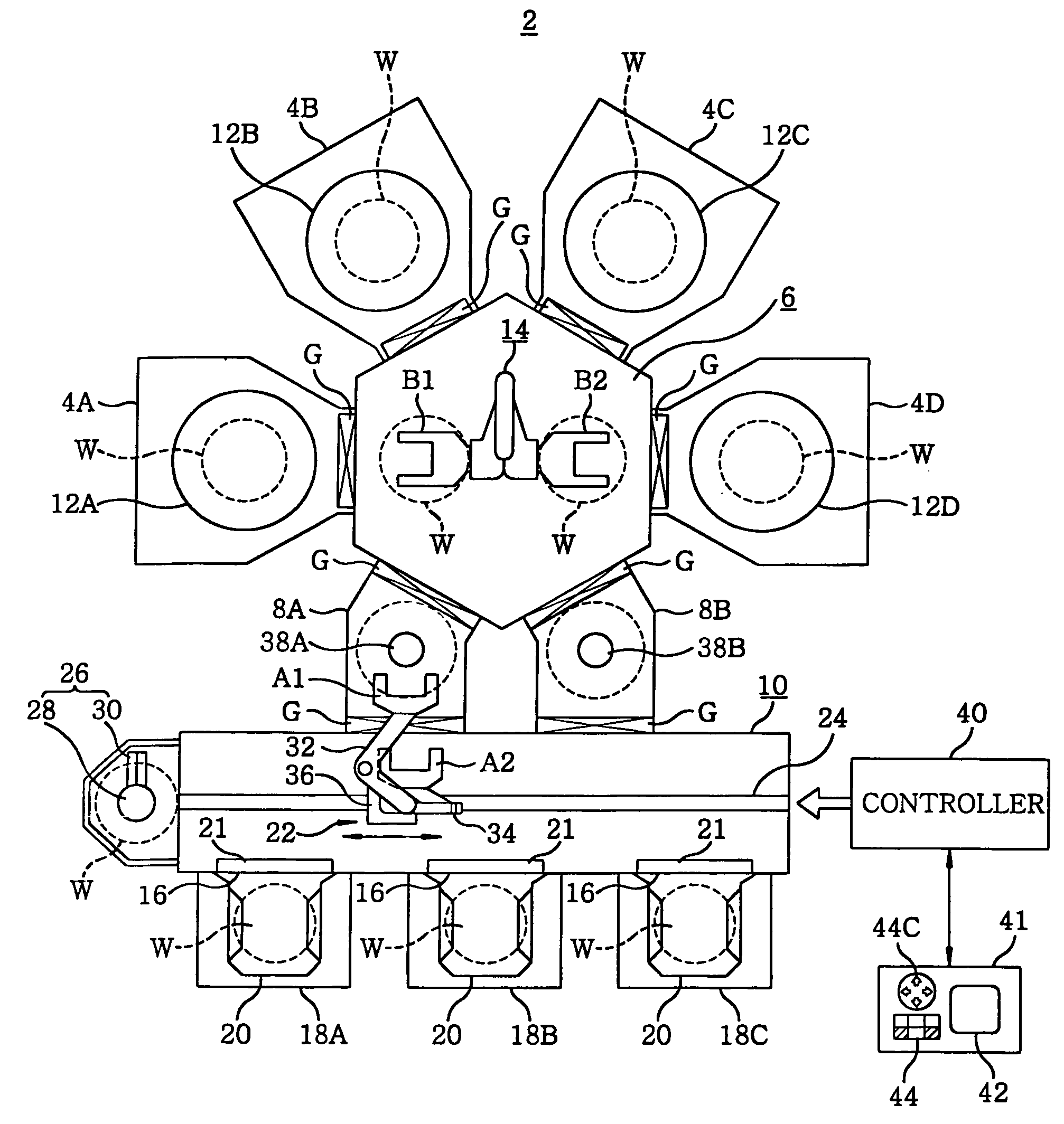
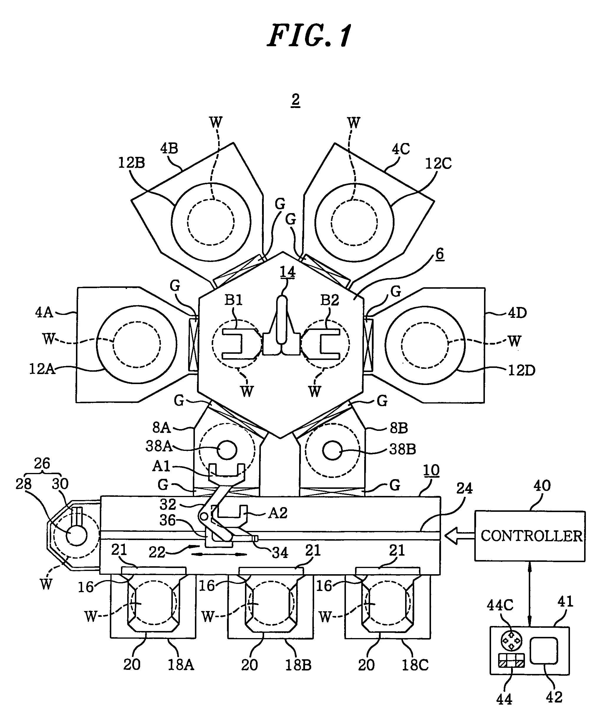
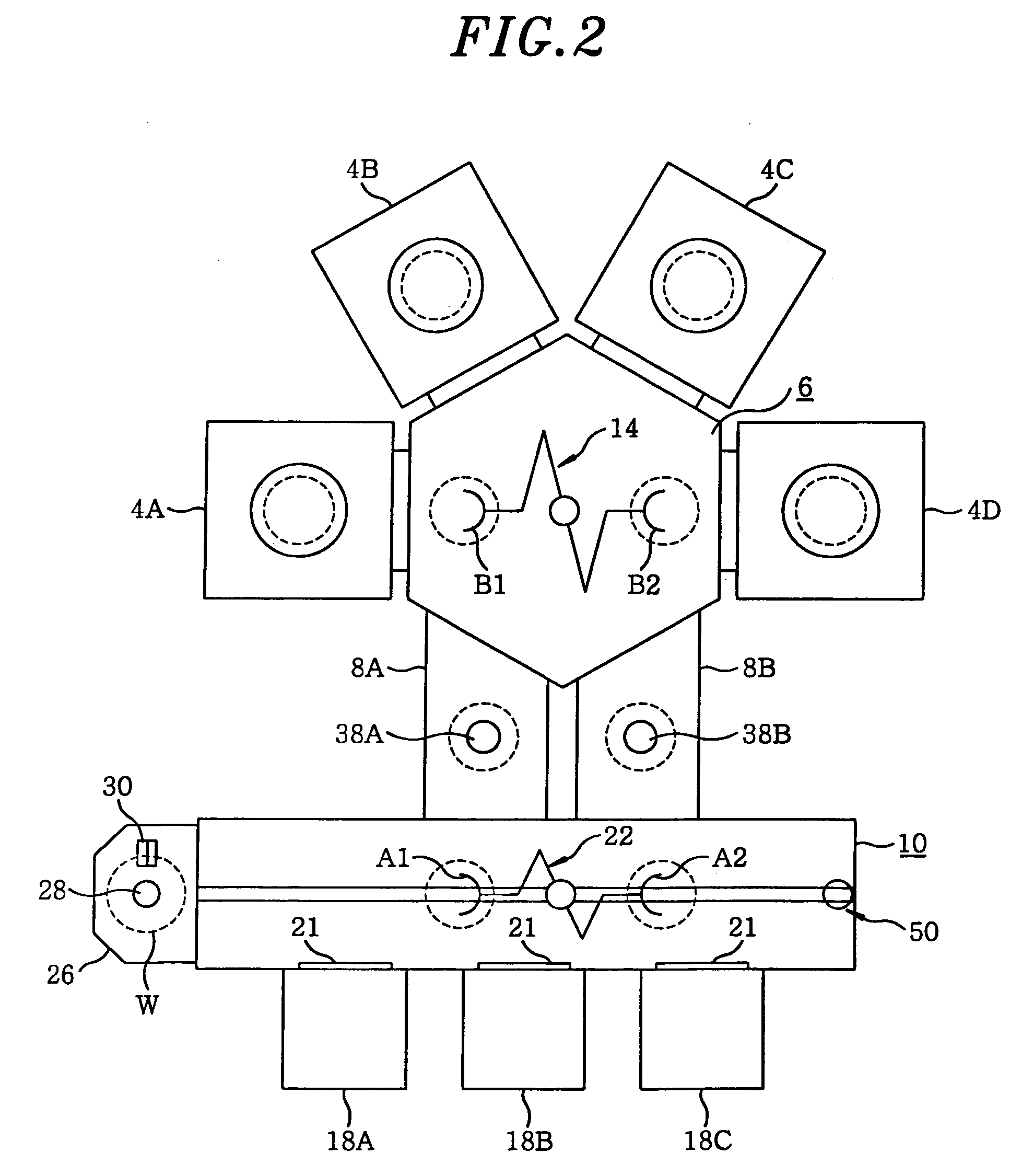
[0074]FIGS. 7A to 7E show an exemplary teaching operation performed for the inlet port in accordance with a first preferred embodiment of a method of the present invention, and FIG. 8 illustrates a flowchart depicting a flow of a teaching method of the present invention. Referring to FIGS. 7A to 7E, there is illustrated a case where a teaching operation of one pick A1 of the first transfer mechanism 22 is performed for a central inlet port 18B among three inlet ports 18A to 18C. In this case, a position aligning substrate W formed in the same size and shape of a semiconductor wafer is mounted on a lowest supporting bracket (not shown) of the cassette container 20, and a position (FIG. 7D) where the pick A1 accesses right under the position aligning substrate W is assumed to be a temporary moving destination position. Further, if the position ...
second preferred embodiment
[0087] Although the exemplary teaching operation performed for the inlet port has been described in the first preferred embodiment, an exemplary teaching operation performed for an orienter will be described in a second preferred embodiment.
[0088]FIGS. 9A to 9D show the exemplary teaching operation performed for the orienter in accordance with the second preferred embodiment of the present invention. Further, FIGS. 9A to 9D partially provide top views. Also in the second embodiment, a teaching operation for the pick A1 of the first transfer mechanism 22 will be described. Further, whenever the pick A1 is temporarily stopped at a potential interference location, the display unit displays thereon a message for informing the operator of a potential interference and the description thereof will be omitted.
[0089] As in the first preferred embodiment, a potential interference location and a temporary moving destination position for the orienter 26 are obtained in advance based on the de...
third preferred embodiment
[0096] Hereinafter, a teaching operation performed for a load-lock chamber in accordance with a third preferred embodiment will be described.
[0097]FIGS. 10A to 10E illustrate an exemplary teaching operation performed for the load-lock chamber in accordance with the third preferred embodiment of the present invention.
[0098] Herein, an operation for teaching the pick A1 with respect to the load-lock chamber 8A between two load-lock chambers 8A and 8B will be described as an example. The position aligning substrate W is mounted in advance on the mounting table 38A in the load-lock chamber 8A. Further, four potential interference locations shown in FIGS. 10A to 10D are obtained based on the design values of the processing system. FIG. 10E presents a temporary moving destination position. Moreover, since the display on the display unit is same as in the aforementioned case, the description thereof will be omitted.
[0099] First, if a moving instruction is inputted by pressing the go but...
PUM
 Abstract
Description
Claims
Application Information
 - R&D
- Intellectual Property
- Life Sciences
- Materials
- Tech Scout
- Unparalleled Data Quality
- Higher Quality Content
- 60% Fewer Hallucinations
Browse by: Latest US Patents, China's latest patents, Technical Efficacy Thesaurus, Application Domain, Technology Topic, Popular Technical Reports.
© 2025 PatSnap. All rights reserved.Legal|Privacy policy|Modern Slavery Act Transparency Statement|Sitemap|About US| Contact US: help@patsnap.com


