Eureka AIR delivers breakthrough ideas for toughest innovation challenges, trusted by R&D personnel around the world.

Flight developer regulating member, developing apparatus and method of assembling developing apparatus

a technology of developing apparatus and developer, applied in the direction of electrographic process apparatus, instruments, optics, etc., can solve the problems of increasing the adhesion of developer to the rear end portion of the latent image, and the assembly time is long, so as to improve the assembly property and high accuracy and simple attachment

Inactive Publication Date: 2005-10-06
CANON KK
View PDF7 Cites 14 Cited by
  • Summary
  • Abstract
  • Description
  • Claims
  • Application Information

AI Technical Summary

Benefits of technology

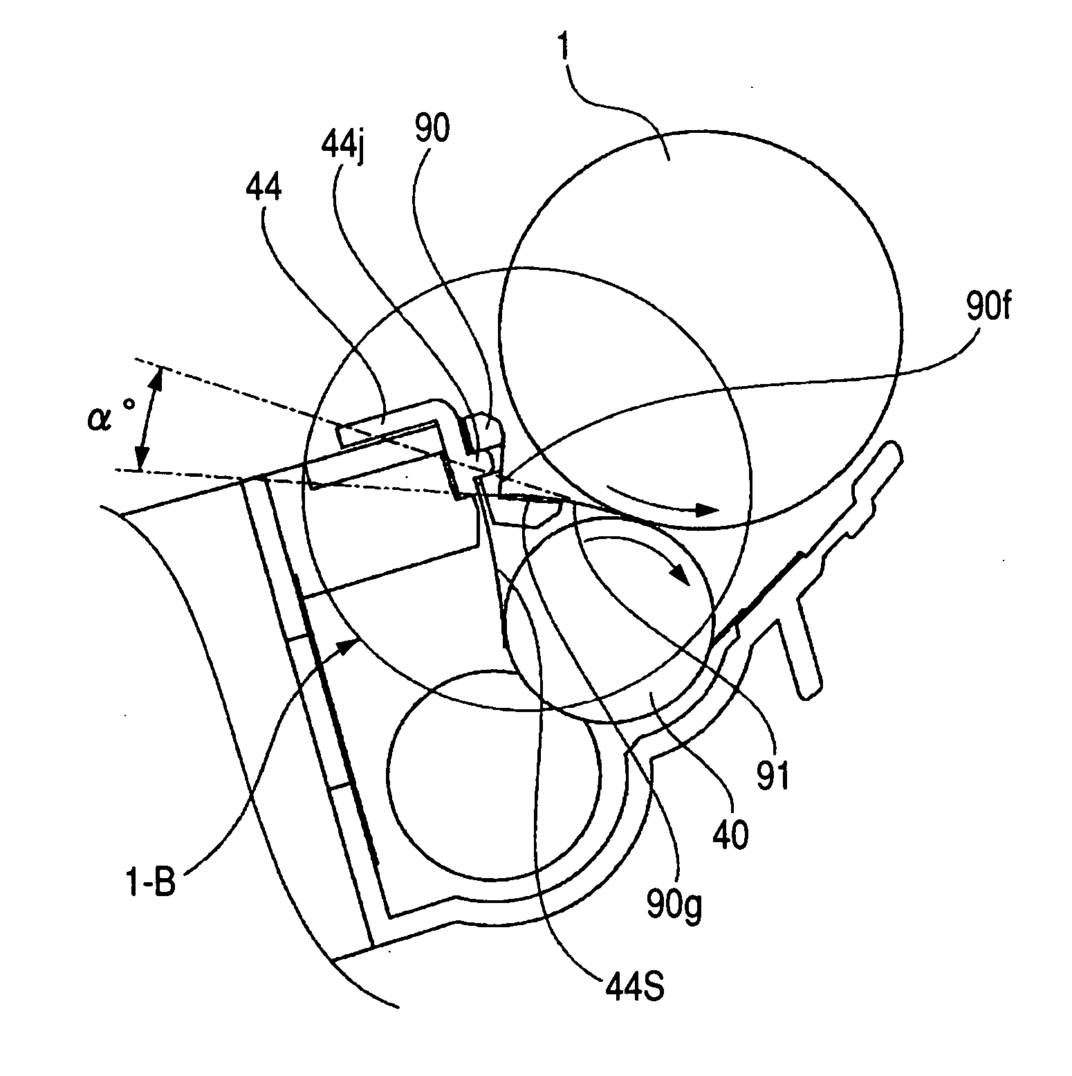
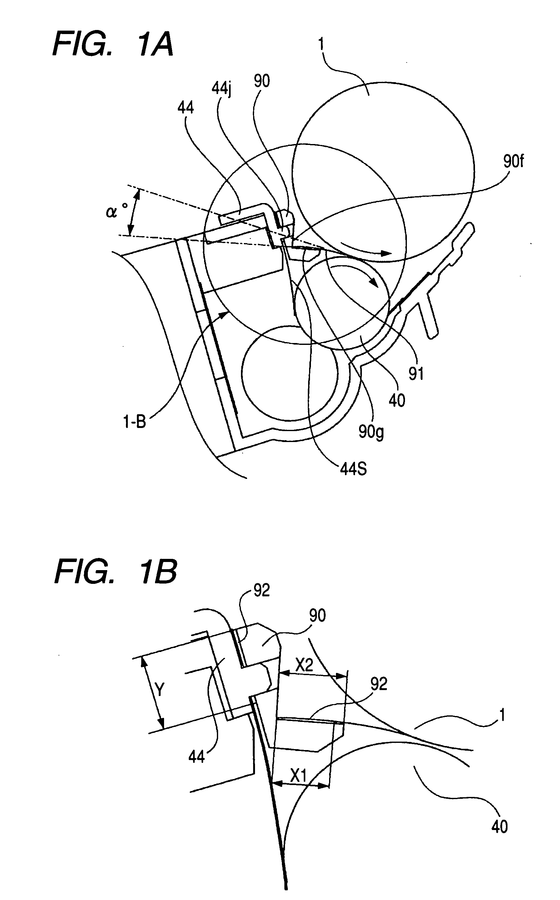
[0009] It is another object of the present invention to provide a flight developer regulating member, a developing apparatus and a method of assembling a developing apparatus which prevent any density change from occurring to an image which should be equal in image density.
[0010] It is another object of the present invention to provide a flight developer regulating member, a developing apparatus and a method of assembling a developing apparatus which suppress the phenomenon that image density becomes high in the trailing edge portion of an image.
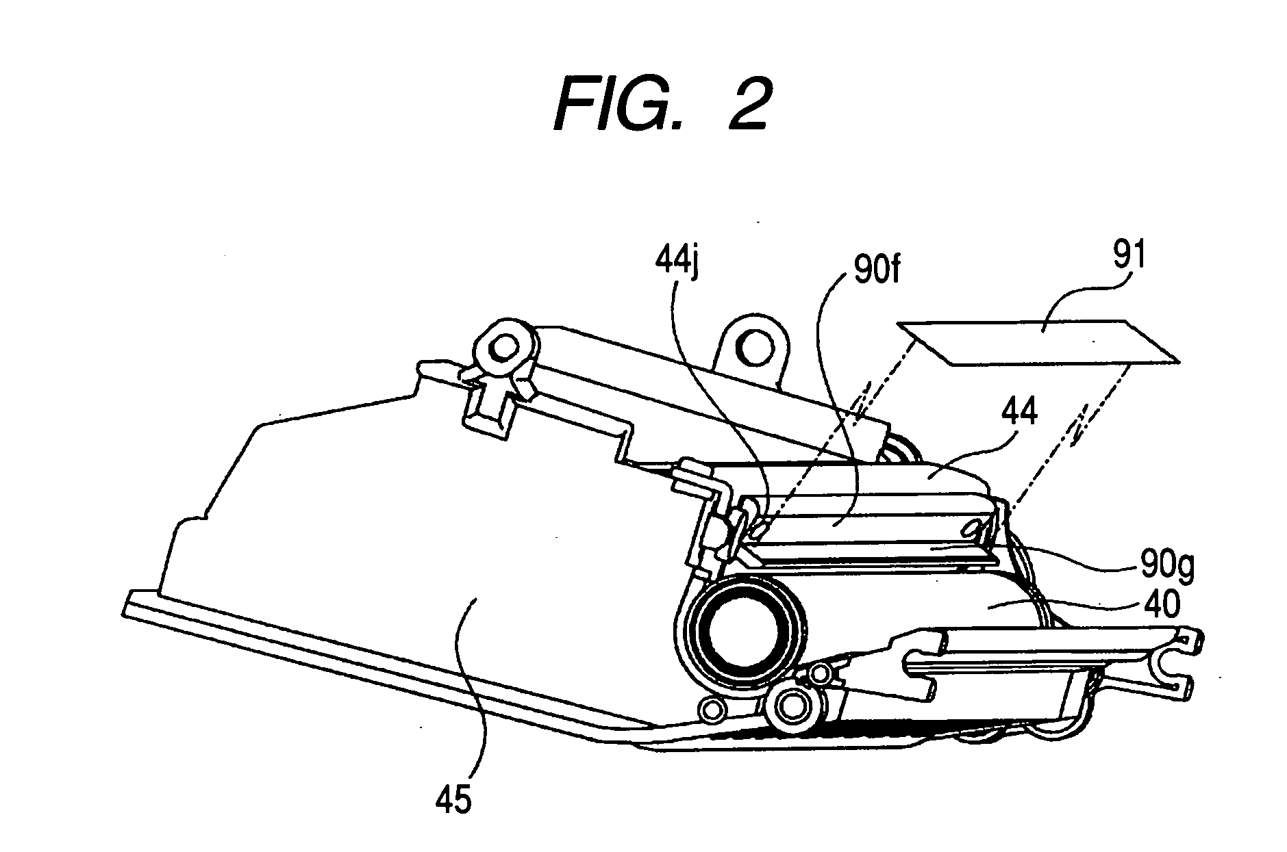
[0011] It is another object of the present invention to provide a flight developer regulating member which can be highly accurately and simply attached to a developing apparatus, a developing apparatus and a method of assembling a developing apparatus.
[0012] It is another object of the present invention to provide a flight developer regulating member, a developing apparatus and a method of assembling a developing apparatus which can improve the assembling property of the flight developer regulating member and the developing apparatus.

Problems solved by technology

In a case where the developer is thus caused to fly from the developer carrying member to the image bearing member, there has arisen the problem that even if a latent image which should be equal in density is formed on the moving image bearing member, more developer adheres to the rear end portion of the latent image.
The plate-shaped member, however, is disposed in a minute interstice between the developer carrying member and the image bearing member and therefore, the fore end thereof must be attached with high accuracy, and this has led to the problem that much time is required for assembly, and a further improvement has been necessary.

Method used


Image

  • Flight developer regulating member, developing apparatus and method of assembling developing apparatus
  • Flight developer regulating member, developing apparatus and method of assembling developing apparatus
  • Flight developer regulating member, developing apparatus and method of assembling developing apparatus

Examples


Embodiment Construction

[0026] Some embodiments of the present invention will be described with reference to the drawings.

[0027] An embodiment of a multi-color image forming apparatus which can use the developing apparatus of the present invention will first be described in detail with reference to the drawings.

[0028] The general construction of the multi-color image forming apparatus will first be schematically described with reference to FIG. 3. FIG. 3 is a longitudinal cross-sectional view showing the general construction of a full-color laser beam printer 100 which is an embodiment of the multi-color image forming apparatus.

[0029] The multi-color image forming apparatus 100 shown in FIG. 3 is provided with photosensitive drums 1a, 1b, 1c and 1d which are four image bearing members juxtaposed in a vertical direction. Each photosensitive drum 1 is rotatively driven in a counter-clockwise direction in FIG. 3 by driving means (not shown). Around the photosensitive drum 1, there are disposed a charging d...


PUM


Abstract

A developing apparatus including a developer carrying member, a developer layer regulating member and a flight developer regulating member, wherein the developer carrying member is provided in opposed relationship with an image bearing member and carries a developer thereon, and in an opposed portion between the image bearing member and the developer carrying member, an oscillating electric field is formed between the image bearing member and the developer carrying member, and the developer is caused to fly from the developer carrying member to the image bearing member, and the developer layer regulating member regulates a layer of developer on the developer carrying member, and the flight developer regulating member is mounted on the developer layer regulating member, and regulates an area in which the developer flies in the opposed portion.

Description

BACKGROUND OF THE INVENTION [0001] 1. Field of the Invention [0002] The invention relates to a flight developer regulating member, a developing apparatus and a method of assembling a developing apparatus preferably used in an image forming apparatus of an electrophotographic type or an electrostatic recording type. [0003] 2. Related Background Art [0004] There has heretofore been adopted a process cartridge method whereby an electrophotographic photosensitive member, charging means, developing means, cleaning means, etc. are integrally made into a cartridge, which is made detachably mountable on an image forming apparatus main body. By this cartridge method, operability is more improved and it becomes possible for a user himself to easily effect the maintenance of the above-mentioned process means and therefore, this cartridge method is widely used in image forming apparatuses of the electrophotographic type. [0005] As a developing method in such a process cartridge, there is a deve...

Claims


Application Information

Patent Timeline
Patent Type & Authority Applications(United States)
IPC IPC(8): G03G15/00G03G15/08G03G21/00
CPCG03G15/0812
Inventor TOBA, SHINJIROKAKITANI, MASAKI
Owner CANON KK
Why Eureka
Eureka Blog
Learn More