
Audio signal processing circuit

a signal processing and audio signal technology, applied in the direction of transducer details, amplification control details, stereophonic arrangements, etc., can solve the problems of listener unpleasant feeling and localized sound imag

Inactive Publication Date: 2005-10-06
ONKYO TECH KK
View PDF13 Cites 34 Cited by
  • Summary
  • Abstract
  • Description
  • Claims
  • Application Information

AI Technical Summary

Benefits of technology

[0023] The phase difference of 60 degrees causes the problem that sound image is localized in the direction of the channel whose phase relatively progresses, as in the case of the 90 degrees phase shift processing. The phase difference of 180 degrees (i.e., inverse phase) causes a listener unpleasant feeling as if the ear of the listener is pressurized, which problem is unique to the inverse phase. In contrast, the phase difference of 140 to 160 degrees does not cause an unpleasant feeling unique to the inverse phase or produces sound image localization in the certain direction. As a result, the present invention can prevent sound image of the monophonic signal from localizing in the head of the listener so as to create sound field just as enveloping the listener.
[0040] Thus, the invention described herein makes the possible the advantages of: (1) providing a processing capable of performing the same processing independent of whether the input signals are monophonic or stereophonic, preventing sound image localization in the head of the listener so as to create sound field just as enveloping the listener, and performing a processing which does not compromise the sound quality even when the surround signals are stereophonic; and (2) providing a shuffler type filter having a simple structure and a high accuracy.

Problems solved by technology

The phase difference of 60 degrees causes the problem that sound image is localized in the direction of the channel whose phase relatively progresses, as in the case of the 90 degrees phase shift processing.
The phase difference of 180 degrees (i.e., inverse phase) causes a listener unpleasant feeling as if the ear of the listener is pressurized, which problem is unique to the inverse phase.

Method used


Image

  • Audio signal processing circuit
  • Audio signal processing circuit
  • Audio signal processing circuit

Examples


Embodiment Construction

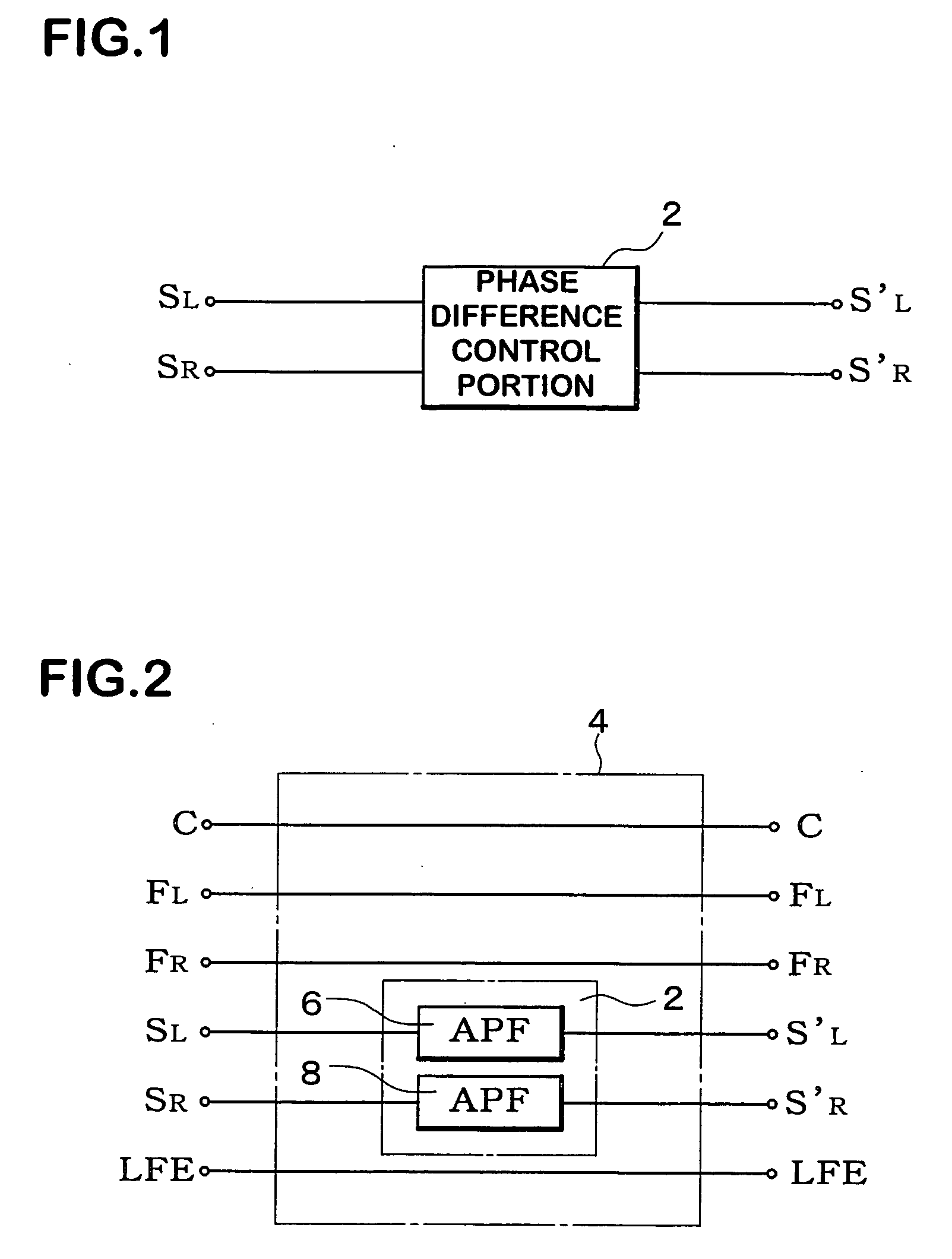
[0073]FIG. 1 is a block diagram of an audio signal processing circuit according to an embodiment of the present invention. The audio signal processing circuit includes a phase difference control portion 2. The phase difference control portion 2 receives a left channel signal SL for a left sound source SSL located substantially at a left side to a listener (shown in FIG. 5) and a right channel signal SR for a right sound source SSR located substantially at a right side to the listener (also shown in FIG. 5). The phase difference control portion 2 controls a phase difference between the left and right channel signals SL and SR so that the relative phase difference be from 140 degrees to 160 degrees (and preferably about 150 degrees) and outputs the phase difference controlled signals S′L and S′R for the left and right sound source, respectively.

[0074] The signals S′L and S′R processed in the above-mentioned manner are respectively supplied to the sound sources SSL and SSR. As a resul...


PUM


Abstract

An audio signal processing circuit for an audio reproduction apparatus at least having sound source located substantially at left and right sides to a listener, is provided. The audio signal processing circuit includes a phase difference control portion. The phase difference control portion receives a left channel signal for the left sound source and a right channel signal for the right sound source, controls a phase difference between the left and right channel signals so as to produce a relative phase difference in the range of 140 degrees to 160 degrees, and outputs the phase difference controlled left and right channel signals for the left and right sound source, respectively.

Description

CROSS-REFERENCE TO RELATED APPLICATIONS [0001] The disclosure of Japanese Patent Application Nos. Hei 10-217929 and Hei 10-218128 both filed on Jul. 31, 1998 including specification, claims, drawings and summary is herein incorporated by reference in its entirety. BACKGROUND OF THE INVENTION [0002] 1. Field of the Invention [0003] The present invention relates to an audio signal processing circuit in a so-called surround system. More particularly, the present invention relates to simplification of its structure, improvement of accuracy, and localization of sound image. [0004] 2. Description of the Related Art [0005] Recently, an audio reproduction apparatus having surround channels at a left and a right sides to a listener in addition to a left and a right (and optionally a center) front channels, has been developed not only for business use but also for home use. In the surround reproduction utilizing such apparatus, two of surround speakers are usually arranged at the both sides (...

Claims


Application Information

Patent Timeline
IPC IPC(8): H04S1/00H04S3/00
CPCH04S1/002H04S2400/01H04S3/002H04S1/007
Inventor KASAI, JOJITAKEMURA, KAZUMASANAKATAKE, TETSURO
Owner ONKYO TECH KK
Learn More