Structure for attaching striker, having attachment bracket including base and protruding portion

Active Publication Date: 2005-10-06
HONDA MOTOR CO LTD
View PDF4 Cites 3 Cited by
  • Summary
  • Abstract
  • Description
  • Claims
  • Application Information

AI Technical Summary

Benefits of technology

[0008] In view of the above circumstances, an object of the present invention is to provide a structure for attaching a striker, wherein the attachment and positioning can be easily performed without a high level of skill.
[0013] According to the above structure, in order to mount a striker, what is necessary is just to attach the striker to the protruding portion which protrudes from the base of the attachment bracket. Therefore, the attachment work can be precisely and easily performed while confirming the positions of the protruding portion and the striker.
[0014] Preferably, the striker has a swelling portion (e.g., a swelling portion 31 in the embodiment) which swells in a direction going away from the base of the attachment bracket. Accordingly, the engaging function necessary in the striker should be secured only in the swelling portion. Therefore, it is unnecessary to secure considerably large portions other than the swelling portion; thus, the attachment bracket can be small, thereby improving the flexibility in the arrangement of the striker.
[0016] Accordingly, the work for positioning the striker can be performed while the cover member is mounted, and additionally, the work hole of the cover member for covering the attachment bracket from the outside of the bracket can be formed at a position which is hidden from the outside, thereby improving the quality of appearance.
[0020] Accordingly, it is possible to position an opening / closing portion, to which the striker is attached, with respect to a vehicle body or the like, by making the striker approach to or retreat from the attachment bracket via the at least one screw member. Therefore, positioning or attachment work can be easily performed.

Problems solved by technology

However, in the above conventional technique in which the striker is attached to a bracket at the back of a vehicle body panel, it is difficult to perform the work of attaching the striker.
In addition, when the attachment work is difficult, accurate positioning is also difficult and an additional or extra fitting or adjustment process may be necessary.

Method used


Image

  • Structure for attaching striker, having attachment bracket including base and protruding portion
  • Structure for attaching striker, having attachment bracket including base and protruding portion
  • Structure for attaching striker, having attachment bracket including base and protruding portion

Examples


Embodiment Construction

[0030] Hereinafter, embodiments according to the present invention will be explained with reference to the drawings.

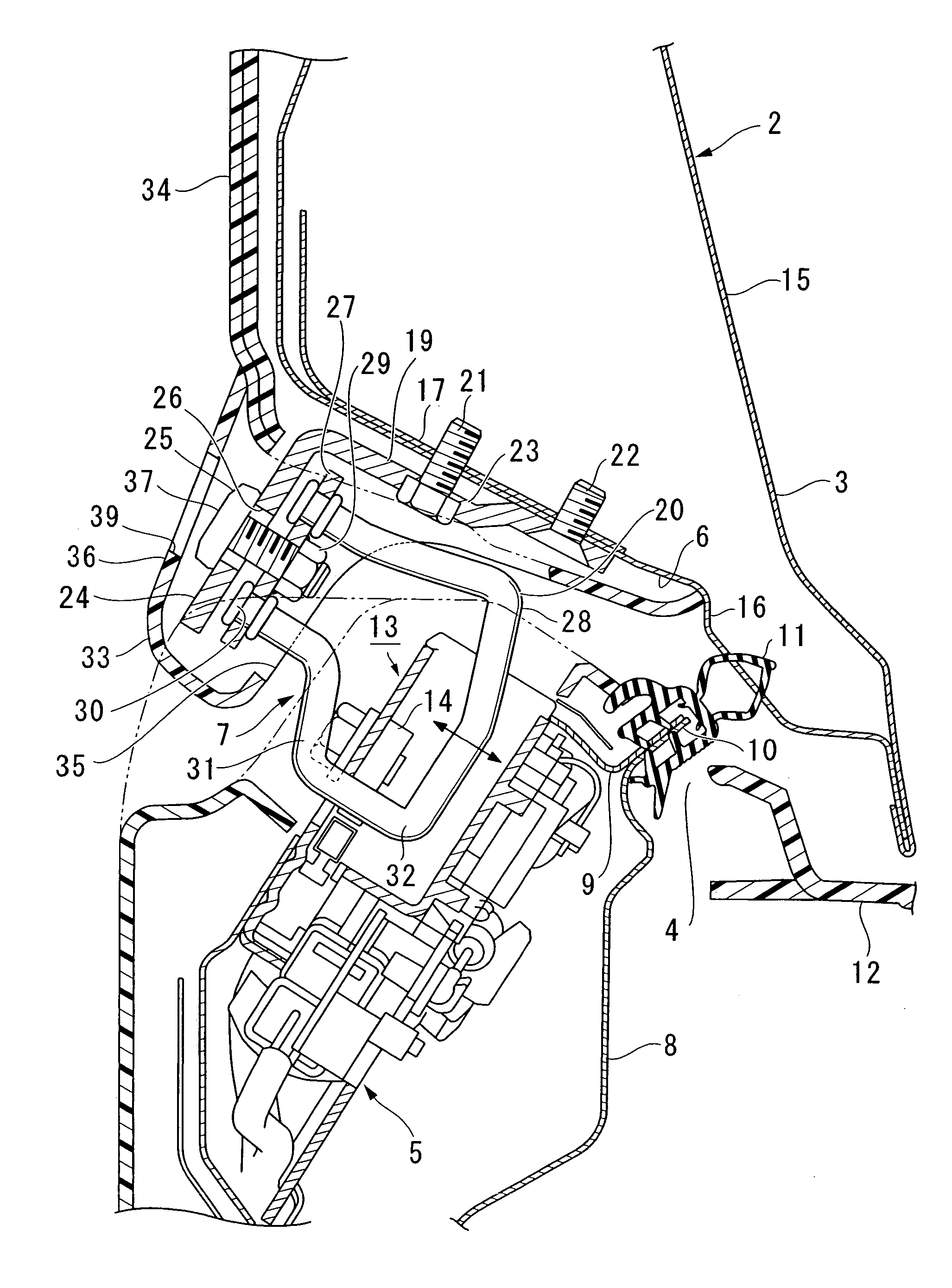
[0031]FIG. 1 is a perspective view showing a rear portion of a vehicle in an embodiment according to the present invention.

[0032] As shown in the figure, in a rear portion of a vehicle body 1, a trunk lid 2 (i.e., a panel (member)) is provided, which can be opened and closed. The trunk lid 2 has a rear wall 3 which extends downward so as to secure a wide space at a rear portion of a trunk opening 4. A locking device 5 is provided at a lower edge of the trunk opening 4, and a striker unit 7 corresponding to the locking device 5 is attached to a lower face 6 of the rear wall 3 of the trunk lid 2.

[0033]FIG. 2 is a sectional view along line A-A in FIG. 1. FIG. 3 is a perspective view showing a main portion including a striker unit, viewed from the bottom, the cover member not being shown. As shown in FIGS. 2 and 3, a reinforcement 9 is joined to a rear end panel 8 at a ...


PUM


Abstract

A structure for attaching a striker, having an attachment bracket including a base fastened to a panel, and a protruding portion joined to the base. The protruding portion extends in a direction different from a direction in which the base is arranged. The striker may have a swelling portion which swells in a direction going away from the base, and is attached to the protruding portion. The structure may include a cover member for covering an outside of the attachment bracket, and a work hole for adjusting the position of the striker is formed in the cover member. Typically, the striker has a base plate and a striker main portion. The base plate is selectively approachable to and retreatable from the attachment bracket via screw members which are inserted through a through hole provided in the protruding portion of the attachment bracket and are adjustably screwed into the base plate.

Description

BACKGROUND OF THE INVENTION [0001] 1. Field of the Invention [0002] The present invention relates to a structure for attaching a striker for vehicles such as cars. [0003] Priority is claimed on Japanese Patent Application No. 2004-112198, filed Apr. 6, 2004, the content of which is incorporated herein by reference. [0004] 2. Description of Related Art [0005] In an example of the structure for attaching a striker, the striker is tightened and fastened to a bracket which is provided at the back of a vehicle body panel. [0006] Generally, the striker is attached in the final process of assembly of a vehicle body. More specifically, the striker is fastened after final fitting such as accurately positioning a door or a trunk lid in the assembled vehicle body is completed (see Japanese Unexamined Patent Application, First Publication No. 2001-152712). [0007] However, in the above conventional technique in which the striker is attached to a bracket at the back of a vehicle body panel, it is...

Claims


Application Information

Patent Timeline
IPC IPC(8): B62D25/12E05B83/18E05B15/02E05B79/08E05B85/04
CPCE05B85/045E05B15/024Y10T292/699Y10T292/705Y10T292/694
Inventor MIYAKE, YOSHINORIYAMADA, KAZUHIKOMUNENAGA, KENICHI
Owner HONDA MOTOR CO LTD
Why Eureka
Try Eureka