
Analytical simulator and analytical simulation method and program

an analytical simulator and simulator technology, applied in the field of analytical simulators and analytical simulation methods and programs, can solve the problems of time-consuming, difficult and time-consuming determination of defective parts, and a skilled technique or a very long working time, and achieve the effect of accurate determination in a short time and efficient device design

Inactive Publication Date: 2006-07-11
UNITED MICROELECTRONICS CORP
View PDF21 Cites 2 Cited by
  • Summary
  • Abstract
  • Description
  • Claims
  • Application Information

AI Technical Summary

Benefits of technology

[0008]In consideration of the above circumstances, an object of the present invention is to provide an analytical simulator and analytical simulation method and program for determining a defective portion in a device in a short time without requiring a high level of experience and skill.
[0056]According to the present invention, the device designed by the design section is tested as a target object to be analyzed, and the output of each test and the output value calculated for the target object by the design section are compared with each other. The defective portion of the target object is determined based on the results of tests. Therefore, a defective portion of a device can be accurately determined in a short time without requiring a high level of experience and skill, thereby efficiently designing the device and overcoming failure of the device in a short time.

Problems solved by technology

Therefore, skilled technique or a very long working time is necessary.
Such determination of the defective portion is difficult and time-consuming, in particular, for semiconductor devices having complicated and large-scale logic circuits.

Method used


Image

  • Analytical simulator and analytical simulation method and program
  • Analytical simulator and analytical simulation method and program
  • Analytical simulator and analytical simulation method and program

Examples


embodiment

OPERATION OF EMBODIMENT

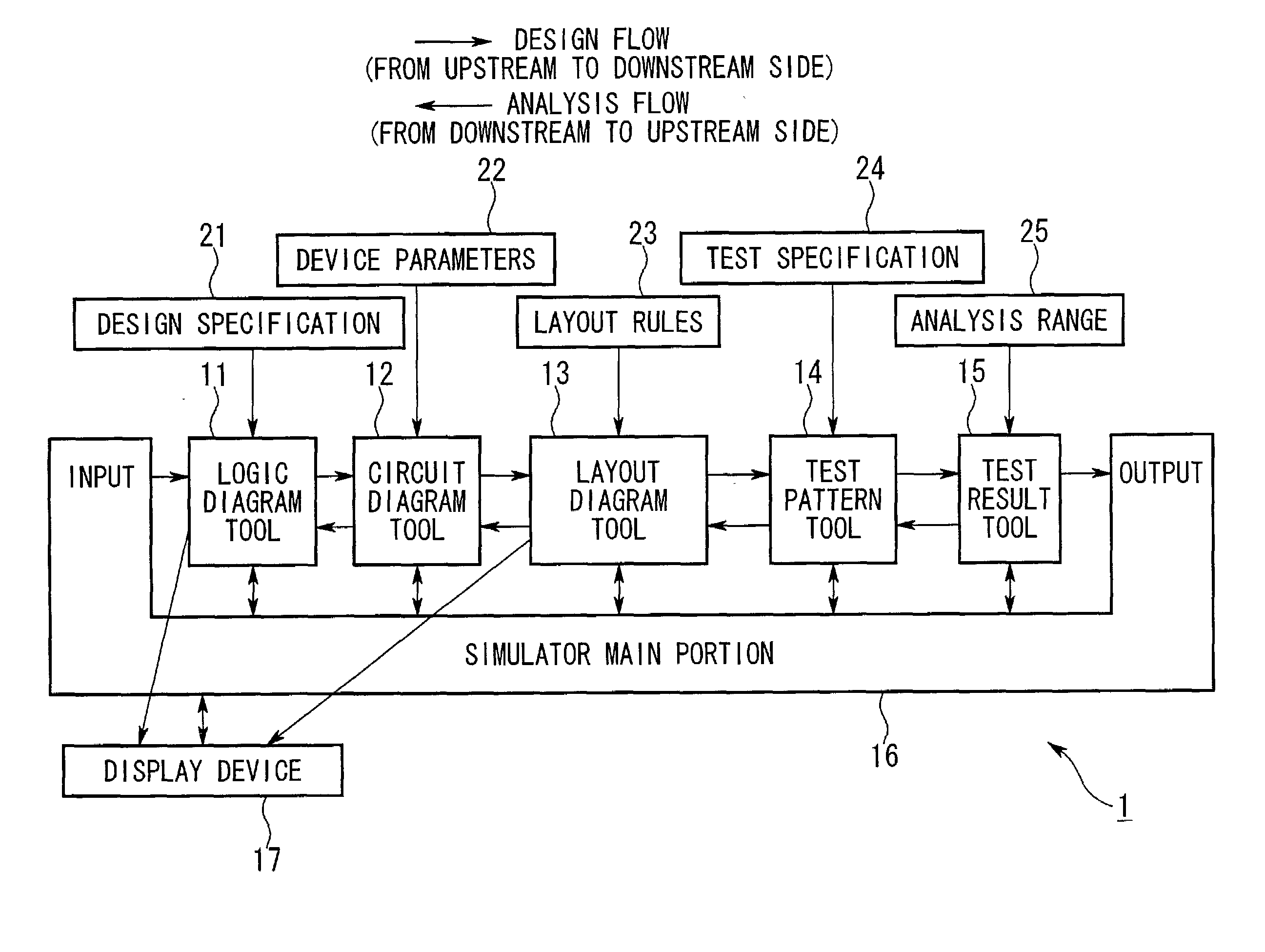
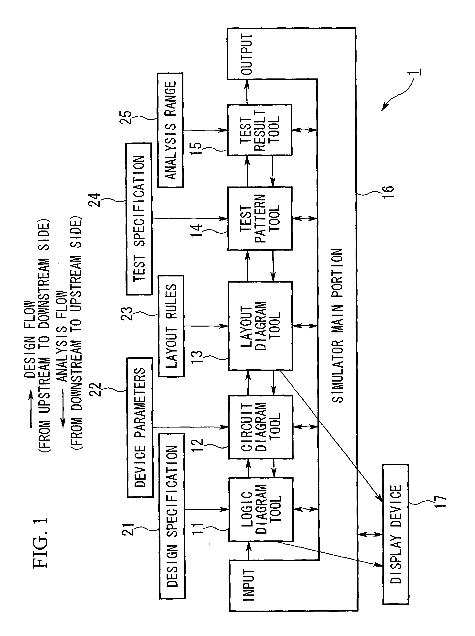
[0077]Below, the operation of the analytic simulator 1 will be explained with reference to FIGS. 1 to 3.

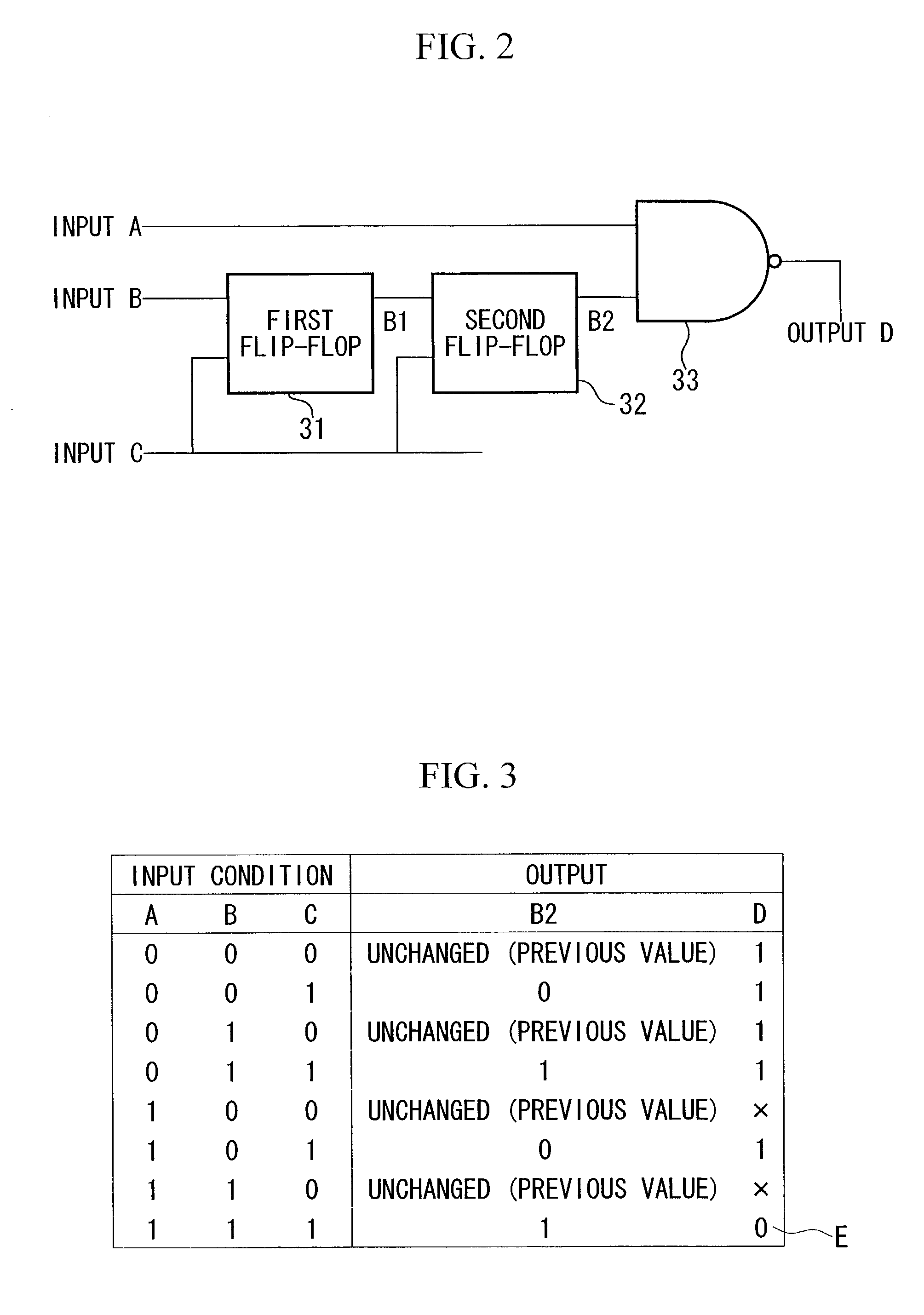
[0078]Here, the circuit shown in FIG. 2 is a target circuit to be analyzed, so as to overcome failure by using the analytic simulator 1. This target circuit is designed in the design flow of the analytic simulator 1, and is actually produced on a semiconductor substrate. Here, it is assumed that the target circuit includes a defective portion.

[0079]The target circuit consists of a first flip-flop 31, a second flip-flop 32, and a NAND circuit 33, and the circuit has three input terminals (input A, input B, and input C) and one output terminal (output D).

[0080]In order to design this target circuit, first, the logic diagram tool 11 of the analytic simulator 1 produces a logic diagram based on the design specification 21. The logic diagram tool 11 then performs logic operations by inputting different data (corresponding to different conditions) into the inputs ...


PUM


Abstract

An analytical simulator and analytical simulation method and program for determining a defective portion in a device in a short time without requiring a high level of experience and skill. The simulator has a design section for designing the device based on predetermined design data including design specification data; a test result tool for receiving results of a test on the device as an object to be analyzed, where the device is designed by the design section and is produced based on the design; and an analysis section for comparing each test result with an expected output value of the object to be analyzed, where the expected output value is calculated by the design section, and for determining a range including a defective portion in the object to be analyzed, based on results of the comparison.

Description

BACKGROUND OF THE INVENTION[0001]1. Field of the Invention[0002]The present invention relates to an analytical simulator and to an analytical simulation method and program used for analyzing failure in an electronic circuit or the like, and in particular, relates to those suitably used for analyzing failure in a semiconductor device.[0003]2. Description of the Related Art[0004]Conventionally, a failure analysis method for detecting a defective portion in a semiconductor device is known, in which a specific signal is input into a logic circuit of the semiconductor device, and the output signal from the logic circuit is electrically measured. If this electrically-measured output signal (i.e., observed value) does not coincide with a logically-calculated output signal (i.e., expected output value) corresponding to the input signal, then it is determined that the logic circuit is defective.[0005]Generally, the logic circuit of the semiconductor device is divided into blocks and a test p...

Claims


Application Information

Patent Timeline
IPC IPC(8): G06F17/50G01R31/28G01R31/3183H01L21/82
CPCG01R31/318342
Inventor ISOBE, SHINOBU
Owner UNITED MICROELECTRONICS CORP
Learn More