Clean Air Toilet System-Tank "C.A.T.S-Tank"

a technology of toilet system and toilet tank, which is applied in the direction of water installation, lavatory sanitory, etc., can solve the problems of inefficiency of standard mechanical ventilation system, clogging of exhaust fan, and affecting the health of residents, so as to achieve less electricity, less cost, and improve the effect of air quality

Inactive Publication Date: 2005-10-06
HANCIULESCO BARBU HORIA
View PDF5 Cites 4 Cited by
  • Summary
  • Abstract
  • Description
  • Claims
  • Application Information

AI Technical Summary

Benefits of technology

[0013] This new type of toilet tank requires a minimum investment and helps to resolve one of today's most important demands with regards to private and public restrooms. The unique features and benefits of the C.A.T.S-Tank are as follows: a) Provides an environmental solution to the emission of polluted air. b) Improve indoor air quality. c) Significantly reduces noise created by the standard Mechanical Ventilation System. d) Is energy efficient (save electricity and water) e) To improve overall quality of living. [How Solve the Current Demands]
[0021] 6. Works automatically, easy to use, no moving parts and reduced noise. The C.A.T.S-Tank starts working automatically when the wall electrical switch in turned “on” the bathroom.

Problems solved by technology

Missing an appropriate air filter. a) Without the protection of an air filter, the Exhaust Fan, located above the ceiling, will get clogged in a short period of time. b) The Odorous Air exhausted from the bathroom is expelled outside into the outdoor environment without a filtration system, which has a significant impact on the environmentally clean air.
Indoor air quality studies found that the air quality inside buildings is more polluted then outdoor air, even during severe air pollution events.
The inefficiency of the standard Mechanical Ventilation System greatly contributes to the unhealthy clean air inside buildings.
As a direct result of these inefficiencies, the use of aerosol sprays and other expensive products are needed to cover up odors.
The use of such room deodorants and other similar products are affecting indoor and outdoor clean air quality.
Energy inefficiency.
The current Exhaust Ventilation System in bathrooms does not save electricity because it needs to be “on” a longer period of time to accomplish its function.

Method used


Image

  • Clean Air Toilet System-Tank "C.A.T.S-Tank"
  • Clean Air Toilet System-Tank "C.A.T.S-Tank"
  • Clean Air Toilet System-Tank "C.A.T.S-Tank"

Examples


Embodiment Construction

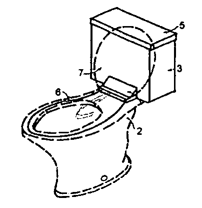
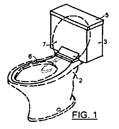
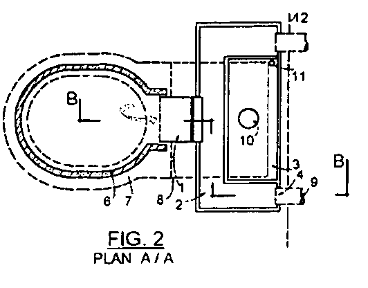
[0030] (1) Air Grille and Odor Filter Element (1) is located in front bottom of the C.A.T.S-Tank. The Air Grille and Odor Filter are built together in one element and are designed to: a) Exhaust the Odorous Air from the Toilet Bowl, before the odor spreads inside the bathroom. b) Clean the Odorous Air before it is released into the exterior environment. c) Protect the C.A.T.S-Tank from clogging. A large selection of materials are currently available for use: Sheet metal, ceramic, plastic, glass, rubber, wood or any other water proof materials which are easy to clean and quite strong. Air Filter is membrane type (nylon having micron sized holes).

[0031] Size: 100 mm. wide / 20 mm. height; Filter size: 100 mm. wide / 60 mm. height The distance between the Air Grille and the Odor Filter will vary depending on the toilet bowl and the toilet seat type. The Air Grille and Odor Filter may need to be replaced every 6 month. Air Grille and Odor Filter is a novel element with an unique function a...


PUM


Abstract

The innovative concept is: “Clean Air Toilet System Tank” or “C.A.T.S-Tank”. The Toilet Tank has dual function: exhausting the Odorous Air directly from the Toilet Bowl, (novel function) and retaining the water for the Toilet Flushing System (standard function). The Tank has two separate compartments: One for Air and one for Water. The Air Compartment is equipped with two Ducts connecting the Air Grille, (mounted on the front bottom of the Tank), with two Back Openings (provided on the back of the Tank). The two Back Openings are connected through duct runs with the existing Exhaust Fan (above ceiling) as part of bathroom Ventilation System. To increase the efficiency of “C.A.T.S-Tank” Air Tight Insulation is provided on the Toilet Bowl rim. The “C.A.T.S-Tank” will be part of the bathroom Ventilation System and in the same time remains part of the Plumbing System.

Description

BACKGROUND OF INVENTION [0001] 1. The Field of Invention [0002] The field of inventive concept is: Mechanical Ventilation with application in the home and public bathrooms [0003] 2. Description of Related Art [0004] At the present the Mechanical Ventilation System for bathrooms requires: a) An Exhaust System (an Exhaust Fan above ceiling) b) An Air Supply System to compensate for the air exhausted in the ventilation process. [0005] As per Mechanical Code, each bathroom without natural ventilation (no exterior windows) needs to be provided with a Mechanical Ventilation System. A Mechanical Ventilation System is necessary to avoid the formation of mold, reduce the fog formation, as well as to remove odor and to improve indoor air quality. [Complain Against Related Art][0006] Inefficient. The present Mechanical Ventilation System requires longer period of time to work, in order to accomplish the following tasks: a) Avoid formation of mold b) Reduce steam c) Improve indoor air quality....

Claims


Application Information

Patent Timeline
IPC IPC(8): E03D9/04E03D9/05
CPCE03D9/05
Inventor HANCIULESCO, BARBU HORIA
Owner HANCIULESCO BARBU HORIA
Why Eureka
Try Eureka