Electro illuminating wire lighted safety vests

Active Publication Date: 2017-05-25
WRIGHT RAYMA CHARLENE
View PDF11 Cites 10 Cited by
  • Summary
  • Abstract
  • Description
  • Claims
  • Application Information

AI Technical Summary

Benefits of technology

This invention is about using a material that looks like wire to emit light. The light is emitted in a way that it looks like it's evenly spread across the surface of the wire. This creates an elongated, uniform light intensity pattern that is easy to see from both sides. The invention uses a special light source that is positioned close to the surface of the wire and emits light in a way that matches the wire's characteristics. This invention allows for better control and mapping of light emitted, resulting in a more uniform and desirable lighting effect.

Problems solved by technology

Hunter and fishermen often hunt and fish with others, but may become separated as they wander the woods or downstream from one another.
Even though these high-visibility safety vests greatly improve the chance that a wearer of the vest will be seen by others, certain limitations still exist.
First, a brightly colored vest may be adequate for certain applications when used in a well-lit environment, but the ability for a colored vest to distinguish a wearer from the surrounding environment greatly diminishes as the ambient light also diminishes.
This attribute of the reflective tape creates a hazard for workers in certain situations.
Additionally, most safety vests described above will not aid sportsmen in keeping within sight of one another once ambient light diminishes to the point that the vest can no longer be seen.
Reflective tape does not help in this situation as the person as the person wearing the vest may be too far away from a person with a light source such as a flashlight.
Additionally, light-emitting diodes (LEDs) are often left unprotected and susceptible to damage.
Like this attempt, most prior art neon simulations have resulted in structures difficult to fabricate and providing a little in the way of weight and handling benefits.
However, the twin attributes of neon lighting, uniformity and brightness, have proven to be difficult obstacles to hurdle as such attempts to simulate neon lighting have largely been stymied by the tradeoffs between light distribution to promote the uniformity and brightness.
While the tubing may be lit by such arrangement is likely to result in a “glowing” tube having insufficient intensity to match that of neon lighting.
The use of point light sources such as LEDs may provide intense light that rival or exceed neon lighting, but when arranged in arrays lack the uniformity needed and unfortunately provide alternate high and low intensity regions in the illuminated surfaces.
Attempts to smooth out the light have resulted in lighting that has unacceptably low intensity levels.

Method used


Image

  • Electro illuminating wire lighted safety vests
  • Electro illuminating wire lighted safety vests
  • Electro illuminating wire lighted safety vests

Examples


Embodiment Construction

[0026]The following description refers to the accompanying drawings, in which, in the absence of a contrary representation, the same numbers in different drawings represent similar elements.

[0027]The present invention now will be described more fully hereinafter with reference to the accompanying drawings, in which illustrative embodiment of the invention are shown. This invention may, however, be embodied in many different forms and should not be construed as limited to the embodiment set forth herein; rather, these embodiments are provided so that this disclosure will be thorough and complete, and will fully convey the scope of the invention to those skilled in the art. Like numbers refer to like elements throughout.

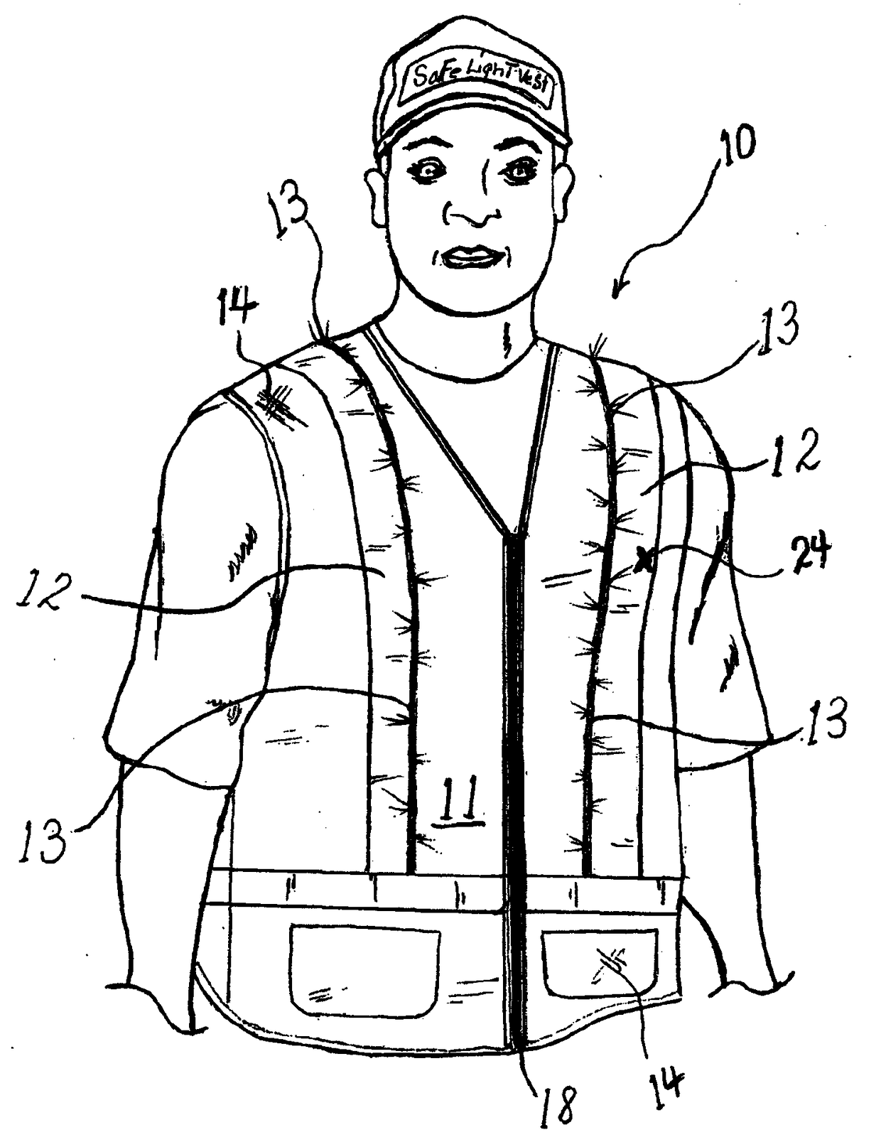
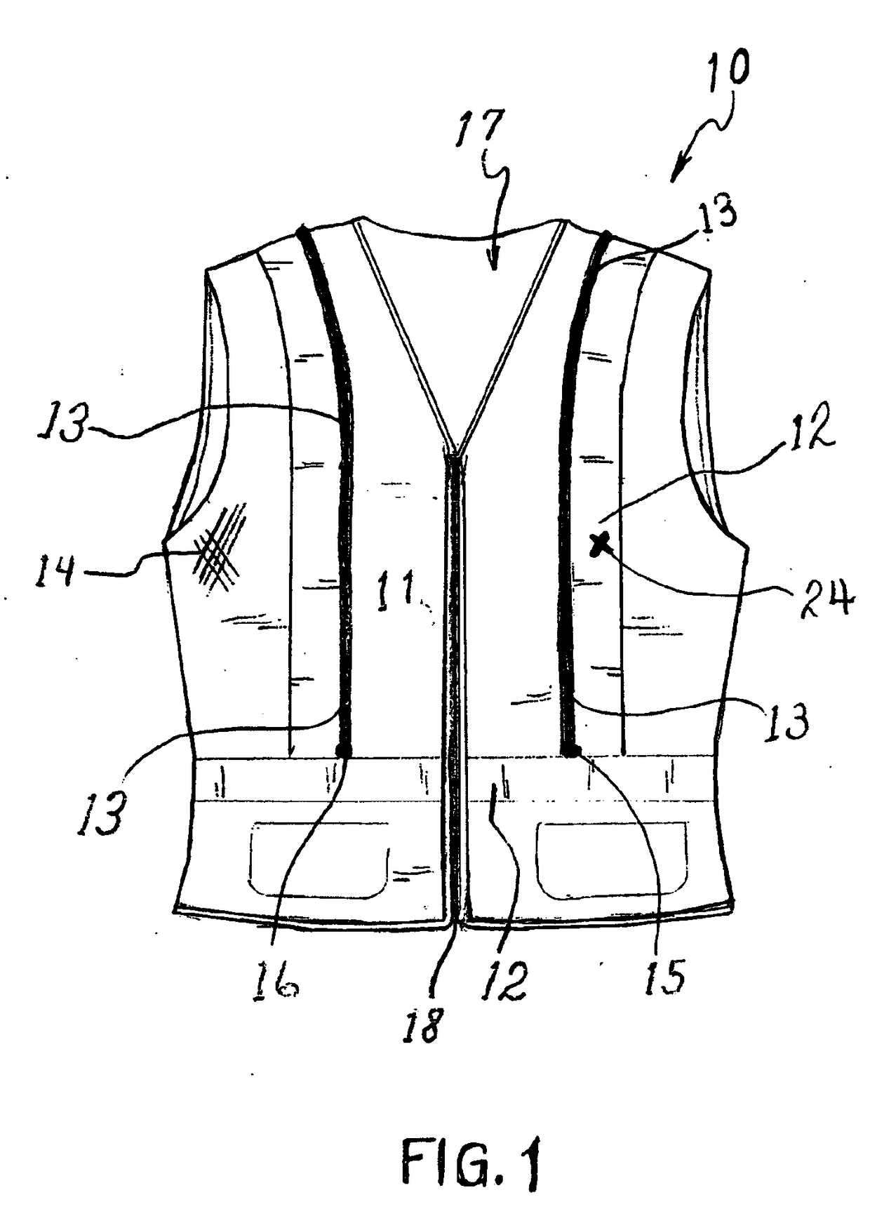
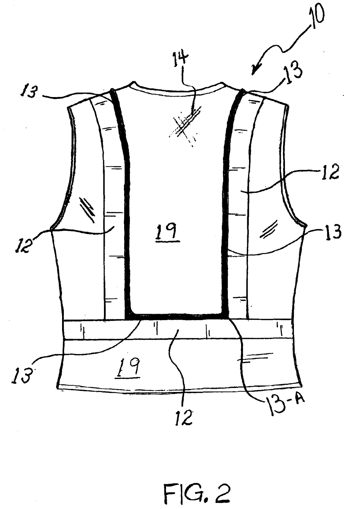
[0028]For the people working or participating in sports or hobbies in close proximity to motor vehicles, aircraft, or other potential dangers, being visible could mean the difference between life and death. Aspects of the present invention provide improved safety vests...


PUM


Abstract

Safety vests and garments are for enhancing the visibility of a wearer in low-light, poor vision conditions. The safety garment has a first reflective layer, a second layer of reflective tape, physically attaching Electro Illuminating Wire under the inside edge of the reflect tape that maybe sewn or glued secures the Electro Illuminating Wire in place. Electro Illuminating Wire is then connected to a standard battery pack of old circuitry. The Electro Illumination Wire and glue are available on the market, Electro Illuminating Wire is old circuitry, prior art. Physically attaching the electro illuminating wire to safety garments creates a new environment, new area for a brighter and versatile safety garment. The electro illuminating wire adds greater visibility to safety garments. Wearers have the option to turn on a bright solid light or bright blinking light, simply by pressing a button, adding even greater visibility to wearers and stopping injury or even death.

Description

CROSS REFERENCE TO RELATED APPLICATIONS[0001]This application is a continuation-in-part application of U.S. application Ser. No. 13 / 915,646 filed Jun. 12, 2013, and claims priority from Provisional Application No. 61 / 661,253 filed Jun. 18, 2012 entitled “El Wire lighted safety vests,” both of which are hereby incorporated by reference in their entirety.BACKGROUND[0002]There are many occupations, sports, and hobbies that require specific safety measures in order to prevent injury. Many of these measures rely on increasing the visibility of a user or location. Specifically, brightly colored vests worn to increase the visibility of a person are typically worn by many workers to enhance their safety. Police officers often wear safety vests when directing traffic or working an accident scene. These vests are often worn over their garments and are made in high-visibility colors such as neon orange, yellow, or green. To increase visibility, these vests often include reflective tape to refl...

Claims


Application Information

Patent Timeline
IPC IPC(8): A41D13/01F21L4/00A41D27/20F21V15/01A41D1/04F21V33/00F21V23/04
CPCA41D13/01F21V33/0008F21L4/00F21V23/0414F21W2121/06A41D1/04A41D27/205F21Y2103/10F21V15/01G08B5/004
Inventor WRIGHT, RAYMA CHARLENE
Owner WRIGHT RAYMA CHARLENE
Why Eureka
Try Eureka