Optical disk recording apparatus and program

a technology of optical disk and recording apparatus, which is applied in the direction of digital signal error detection/correction, instruments, recording signal processing, etc., can solve the problems of different recording power from the actual value, inability to fast start the data recording,

Inactive Publication Date: 2005-09-29
YAMAHA CORP
View PDF6 Cites 4 Cited by
  • Summary
  • Abstract
  • Description
  • Claims
  • Application Information

AI Technical Summary

Benefits of technology

[0019] This computer program can provide the same effect as the inventive construction of the optical disk recording apparatus.
[0020] The present invention makes it possible to radiate laser light with two or more different recording powers to a trial write area (OPC area) of an optical disk, find the relational expression between the laser drive voltage and the recording power, and calculate an accurate initial value of the drive voltage in correspondence with a target recording power. This eliminates problems due to turning off the focus servo during the determination of the relational expression, such as causing a deviation between the actual recording power and the target recording power, and requiring unnecessary time before starting the actual recording. For a example, it is possible to fast set the laser power to an accurate target value based on the relational expression for the subsequent OPC operation.

Problems solved by technology

However, the conventional optical disk recording apparatus turns on the laser to detect a laser drive voltage by forcibly turning off the focus servo to prevent recording on optical disks.
Extra time is needed before starting the OPC, thereby being incapable of fast starting the data recording.
Consequently, recording power Pw is subject to difference ΔP between the first and second cases, thereby causing the problem of making the recording power different from an actual value as mentioned above.

Method used


Image

  • Optical disk recording apparatus and program
  • Optical disk recording apparatus and program
  • Optical disk recording apparatus and program

Examples


Embodiment Construction

[0028] The present invention can be applied to recordable optical disks in general including: recordable CD optical disks such as CD−R and CD−RW; and recordable DVD optical disks such as DVD−R, DVD+R, DVD−RW, DVD+RW, and DVD−RAM. The following description uses CD−R as an example.

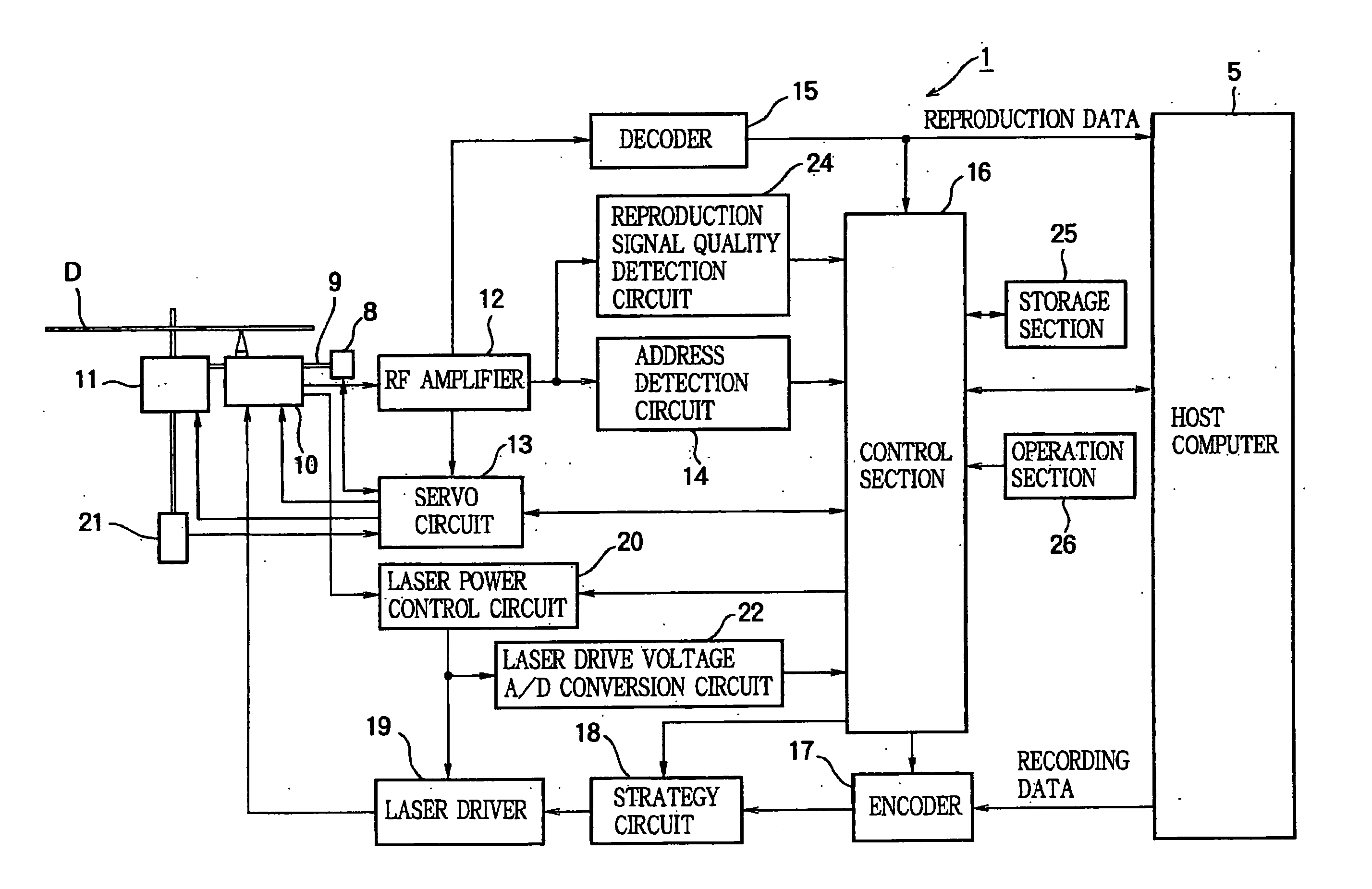
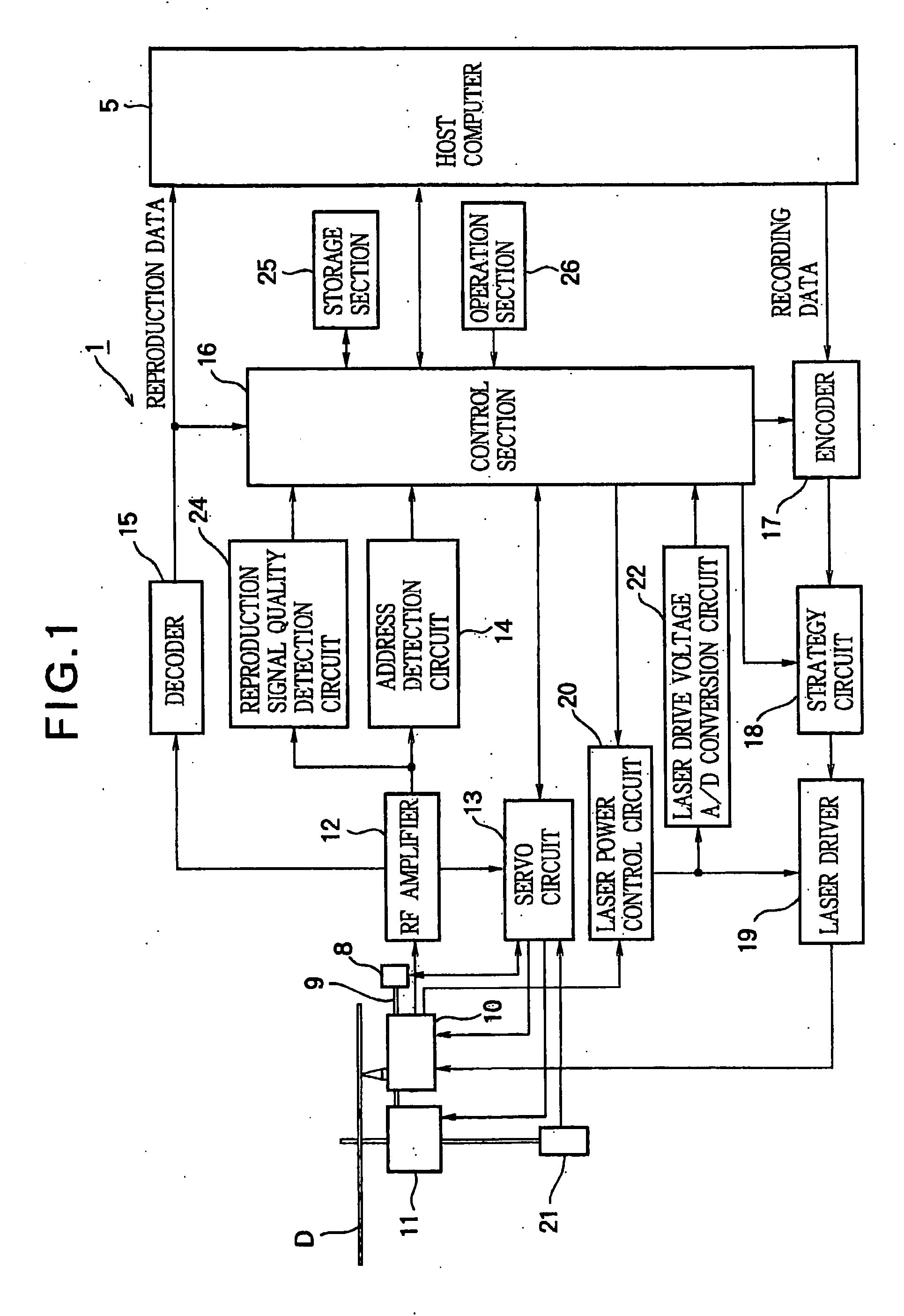
[0029]FIG. 1 is a block diagram showing the schematic configuration of an optical disk recording apparatus according to an embodiment of the present invention. As shown in FIG. 1, an optical disk recording apparatus 1 comprises: a thread motor 8, a guide rail 9, an optical pickup 10, a spindle motor 11, an RF amplifier 12, a servo circuit 13, an address detection circuit 14, a decoder 15, a control section 16, an encoder 17, a strategy circuit 18, a laser driver 19, a laser power control circuit 20, a frequency generator 21, a laser drive voltage A / D conversion circuit 22, a reproduction signal quality detection circuit 24, a storage section 25, and an operation section 26. The optical disk recording appara...


PUM

PropertyMeasurementUnit
recording poweraaaaaaaaaa
voltageaaaaaaaaaa
drive voltageaaaaaaaaaa

Abstract

In an optical disk recording apparatus, a monitor monitors a recording power of a laser light. A laser control circuit enables a laser diode to perform test recording while using the monitor to monitor the recording power of the laser light and while controlling a laser drive voltage, so that the monitored recording power reaches a given reference value during the test recording. A voltage measurement section measures the laser drive voltage when the recording power of the laser light reaches the reference value. A calculation section calculates an initial laser drive voltage from the reference value of the recording power and the measured laser drive voltage corresponding to the reference value. A main controller allows the laser control circuit to set the calculated initial laser drive voltage and to start the recording while supplying the laser control circuit with the target value so that an actual recording power of the laser light promptly reaches the target value during the course of the recording.

Description

BACKGROUND OF THE INVENTION [0001] 1. Technical Field [0002] The present invention relates to an optical disk recording apparatus and an initial laser drive voltage calculation program capable of fast and accurately finding an initial laser drive voltage with reference to a target recording power at the time to start recording. [0003] 2. Related Art [0004] A conventional optical disk recording apparatus finds a relational expression between a laser recording power and a laser drive voltage. Based on the relational expression, the apparatus determines the laser drive voltage to radiate the laser light set to the target recording power. The purpose is to shorten the time in which the laser recording power reaches a target recording power at the beginning of data recording. For example, the optical disk recording apparatus turns on a laser diode using two or more different preset recording powers. The optical disk recording apparatus detects a laser drive voltage at that time to find a...

Claims


Application Information

Patent Timeline
Patent Type & Authority Applications(United States)
IPC IPC(8): G11B7/00G11B7/007G11B7/1263G11B7/1267
CPCG11B7/00736G11B7/1267G11B7/1263
Inventor YAMADA, SEIYA
Owner YAMAHA CORP
Why Eureka
Try Eureka