Liquid crystal display

a liquid crystal display and liquid crystal technology, applied in non-linear optics, instruments, optics, etc., can solve the problems of liquid crystal display having a problem in a change of chromaticity and luminance, and insufficient to display a genuine green imag

Inactive Publication Date: 2005-09-29
MITSUBISHI ELECTRIC CORP
View PDF9 Cites 19 Cited by
  • Summary
  • Abstract
  • Description
  • Claims
  • Application Information

AI Technical Summary

Benefits of technology

[0020] According to the present invention, since a maximum intensity of a light emitting spectrum of a back light is in a range of 510 nm to 530 nm in a wavelength range of 500 nm to 550 nm, a half value range of maximum transmitting rate for the transmitting spectrum of the green color filter is in a wavelength range of 500 nm to 590 nm, and a change of transmitting spectrum at 0° to 60° in a wavelength range of 500 nm to 600 nm of a liquid crystal display panel is relatively within 20% compared with front direction. Therefore, it is possible to display an image with large color reappearance area and a genuine green color with respect to a hue and chroma while controlling a displacement of white chromaticity caused by a change of viewing angle.

Problems solved by technology

However, these green colors are not genuine green colors, but within a range of so-called yellow green, and these hues are not sufficient to display a genuine green image.
In general, the liquid crystal display has a problem in a change of chromaticity and luminance when a direction of a viewing angle of a displayed picture is changed.

Method used


Image

  • Liquid crystal display
  • Liquid crystal display
  • Liquid crystal display

Examples


embodiment 1

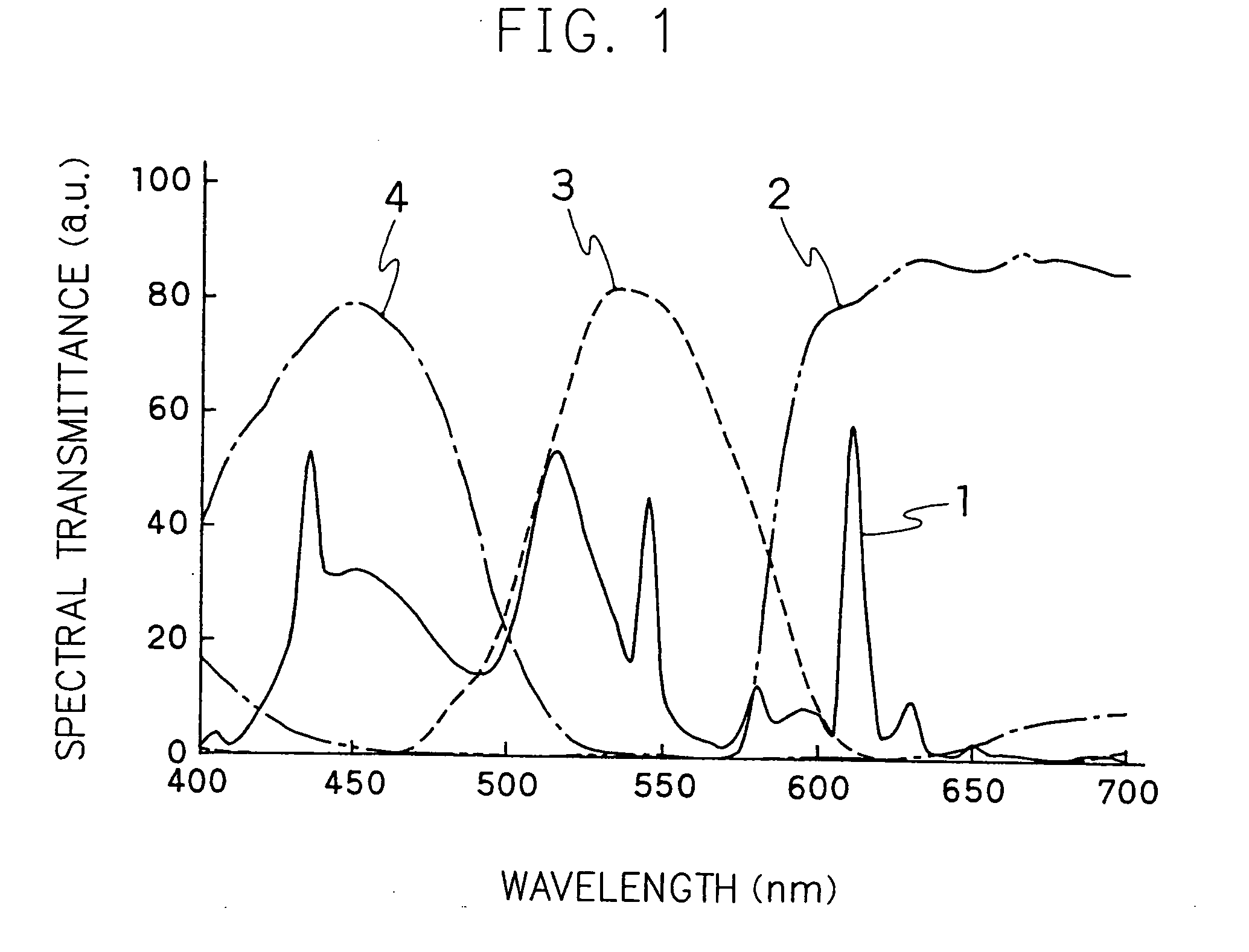
[0033]FIG. 1 shows the characteristic of the light emitting spectrum of a back light BL1 and the characteristic of the transmit spectrum 1 of a color filter CF1 in Embodiment 1. The characteristic of the transmit spectrum is composed of a transmit spectrum 2 of a red color filter, a transmit spectrum 3 of a green color filter and a transmit spectrum 4 of a blue color filter. In Embodiment 1, with respect to a light source for the back light, a cold cathode fluorescent light having a maximum intensity of the light emitting spectrum around 517 nm in a light emitting spectrum range of 500 nm to 550 nm in an area of a green component is employed. On the other hand, a maximum transmission rate of the transmit spectrum of the green color filter 3 is placed around 535 nm, and a wavelength range having a transmission rate of larger than a half value is in a range of 508 nm to 585 nm. For a liquid crystal panel, a general TN-type liquid crystal having the characteristic of the transmit spect...

embodiment 2

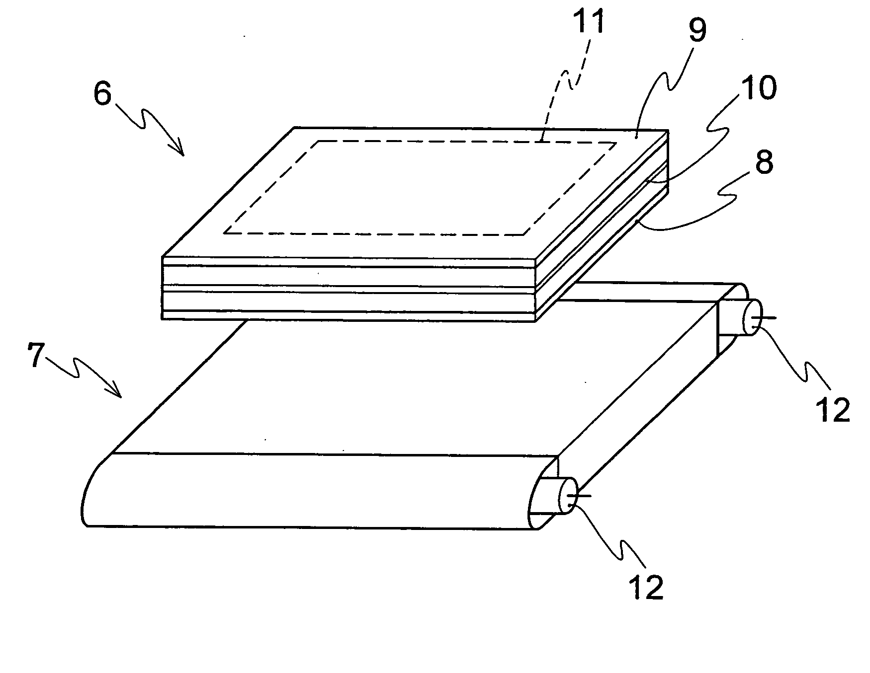
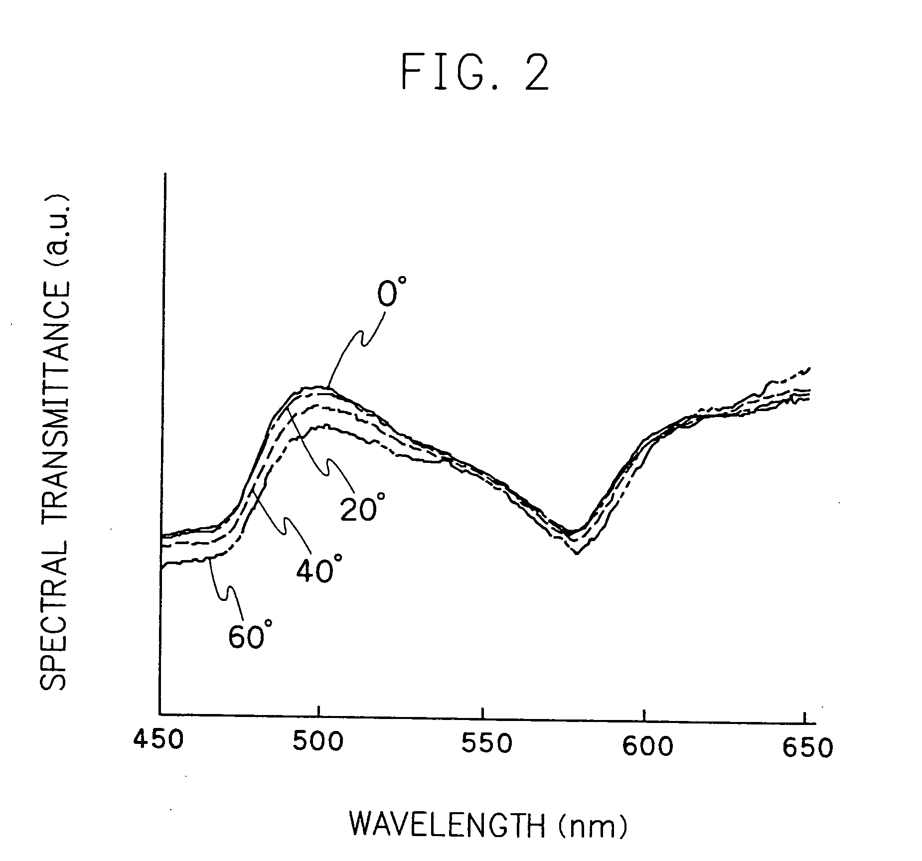
[0038] The liquid crystal display as disclosed in Embodiment 2 is composed of the back light BL1 having the same characteristic of a spectrum and a color filter CF1 as shown in Embodiment 1 and the liquid crystal display panel having a dependent viewing angle of the transmit spectrum as shown in FIG. 2. The viewing angle in FIG. 2 is an angle expressed by a left and right polar angle, as a normal angle in the liquid crystal display is set as 0°. FIG. 3 is a standardized transmit spectrum from each angle of FIG. 2 by spectrum of front direction, and when the change of the viewing angle is between 0° and 60°, a relative change of the transmit spectrum is within 20% of difference. For the liquid crystal display having a transmit spectrum such as in FIGS. 2 and 3, there is employed an IPS mode in which through an electrode located under a substrate, the lateral electric field is applied, then liquid crystal molecules are rotated parallel to the substrate.

[0039] In Table 2, there is sho...

embodiment 3

[0041]FIG. 4 shows a characteristic of a light emitting spectrum 5 of the back light BL2 and a transmit spectrum of a color filter CF1 in Embodiment 3 of the present invention. The color filter CF1 is the same device employed in previous Embodiments 1 and 2, and the same TN-type liquid crystal display panel being employed in Embodiment 1 is employed as a liquid crystal display panel.

[0042] On the other hand, as a light source of the back light, a maximum intensity of the light emitting spectrum of 525 nm at a range of 500 nm to 550 nm of the light emitting spectrum in a green component is used. As the light source, for instance, there can be employed a green light emitting diode (LED) having the same kind of spectrum characteristic. Other than the green LED, white light, a mixture of three light colors of a red LED, blue LED and green LED, can be used. The number of LED is decided to obtain a desirable white chromaticity according to a characteristic of each LED.

[0043] In Table 3,...


PUM

PropertyMeasurementUnit
wavelength rangeaaaaaaaaaa

Abstract

A primary object of the present invention is to provide a liquid crystal display device being capable of displaying an image with large color reappearance area and a genuine hue and chroma, while controlling a displacement of white chromaticity caused by changes of viewing angles. The device includes: a light source; a back light controlling a luminous intensity distribution from the light source; and a liquid crystal display panel controlling a transmission rate of light from the back light. The maximum intensity of a light emitting spectrum of the back light is in a range of 510 nm to 530 nm in a wavelength range of 500 nm to 550 nm, wherein the liquid crystal panel includes a red color filter transmitting red components, a green color filter transmitting green components and a blue color filter transmitting blue components, and a transmit spectrum of the green color filter includes a half value of a maximum transmitting rate of 500 nm to 590 nm in a wavelength range. The change of the transmit spectrum between viewing angle of 0° and 60° is within 20% from front direction in a wavelength range of 500 nm to 600 nm.

Description

BACKGROUND OF THE INVENTION [0001] The present invention relates to a liquid crystal display comprising a liquid crystal display panel and a back light. More particularly, the present invention relates to the liquid crystal display which requires excellent color reappearance and visibility. [0002] Recently, the liquid crystal display is used widely because of its advantages of lightness, thinness and low electric power usage, and replaces CRT which has been used. [0003]FIG. 5 is a perspective view showing an arrangement of a general liquid crystal display. In FIG. 5, numeral 6 is a liquid crystal panel, numeral 7 is a back light unit. On the liquid crystal panel 6, there are provided a TFT element, lines and a TFT substrate 8 on which electrodes are formed, and a counter substrate 9 having a color filter on glass and aligned parallel and a liquid crystal 10 therebetween. An area 11 in the liquid crystal panel 6 is composed of a plurality of pixels, and each pixel comprising subpixel...

Claims


Application Information

Patent Timeline
Patent Type & Authority Applications(United States)
IPC IPC(8): G02F1/139G02F1/1335G02F1/13357G02F1/1337
CPCG02F1/133609G02F1/133514
Inventor NAKANISHI, KUNIFUMI
Owner MITSUBISHI ELECTRIC CORP
Why Eureka
Try Eureka