Radiation detector and a method of manufacturing the detector

a technology of a detector and a manufacturing method, applied in the field of radiation detectors, can solve the problems of reducing the capability of discriminating and thus detecting, the position of incidence of gamma rays, and the complexity of the manufacturing process, so as to avoid the effect of lowering the resolution

Inactive Publication Date: 2005-09-29
SHIMADZU CORP
View PDF9 Cites 24 Cited by
  • Summary
  • Abstract
  • Description
  • Claims
  • Application Information

AI Technical Summary

Benefits of technology

[0028] In the above radiation detector manufacturing method, it is preferred that a release agent is applied to the rectangular vessel before executing the step (B) of pouring the transparent liquid resin into the rectangular vessel. Then, when executing the step (D), i.e. removing from the rectangular vessel a cured resin object integrating the liquid resin having cured, the lattice frame and the scintillators, and contouring the resin object to make the scintillator array, the resin object may be removed from the rectangular vessel easily.
[0029] Preferably, the liquid resin is defoamed when executing the step (B) of pouring the transparent liquid resin into the rectangular vessel. By defoaming the liquid resin, the cured resin becomes free from voids formed therein, thus avoiding lowering of resolution due to such voids. As a defoaming method, the liquid resin may be poured in after being defoamed, or the liquid resin may be poured in while carrying out vacuum degassing, after placing the rectangular vessel in a space that may be vacuum-degassed.

Problems solved by technology

This reduces the capability of discriminating, and thus detecting, positions of incidence of gamma rays.
This will results in a complicated manufacturing process, and thus high cost.
When suitable light reflecting elements DA are inserted in the slits MA after a shaping process, gaps are formed between the reflecting elements DA and slits MA, thereby lowering reflection efficiency also.
As these factors reduce output by incident gamma rays to make an accurate discrimination of positions impossible, an overall image quality will also deteriorate.
More particularly, a reduced discriminating ability results in a reduction in resolution.
Where such radiation detector RDA is used in a medical diagnostic apparatus such as a PET apparatus or SPECT apparatus, images obtained by the apparatus will have poor quality.
When a region of interest is a tumor, for example, the tumor may not be accurately outputted on the image.
Further, the light reflecting elements DA or light transmitting elements inserted or filled as optical elements between the scintillator S make an accurate discrimination of positions even more difficult, particularly where light transmitting elements are used.
However, since the optical adhesive forms adhesive layers, it is difficult to control the thickness of the light transmitting elements.
This further encumbers an accurate discrimination of positions of gamma ray incidence.

Method used


Image

  • Radiation detector and a method of manufacturing the detector
  • Radiation detector and a method of manufacturing the detector
  • Radiation detector and a method of manufacturing the detector

Examples


Embodiment Construction

[0041] A preferred embodiment of this invention will be described in detail hereinafter with reference to the drawings.

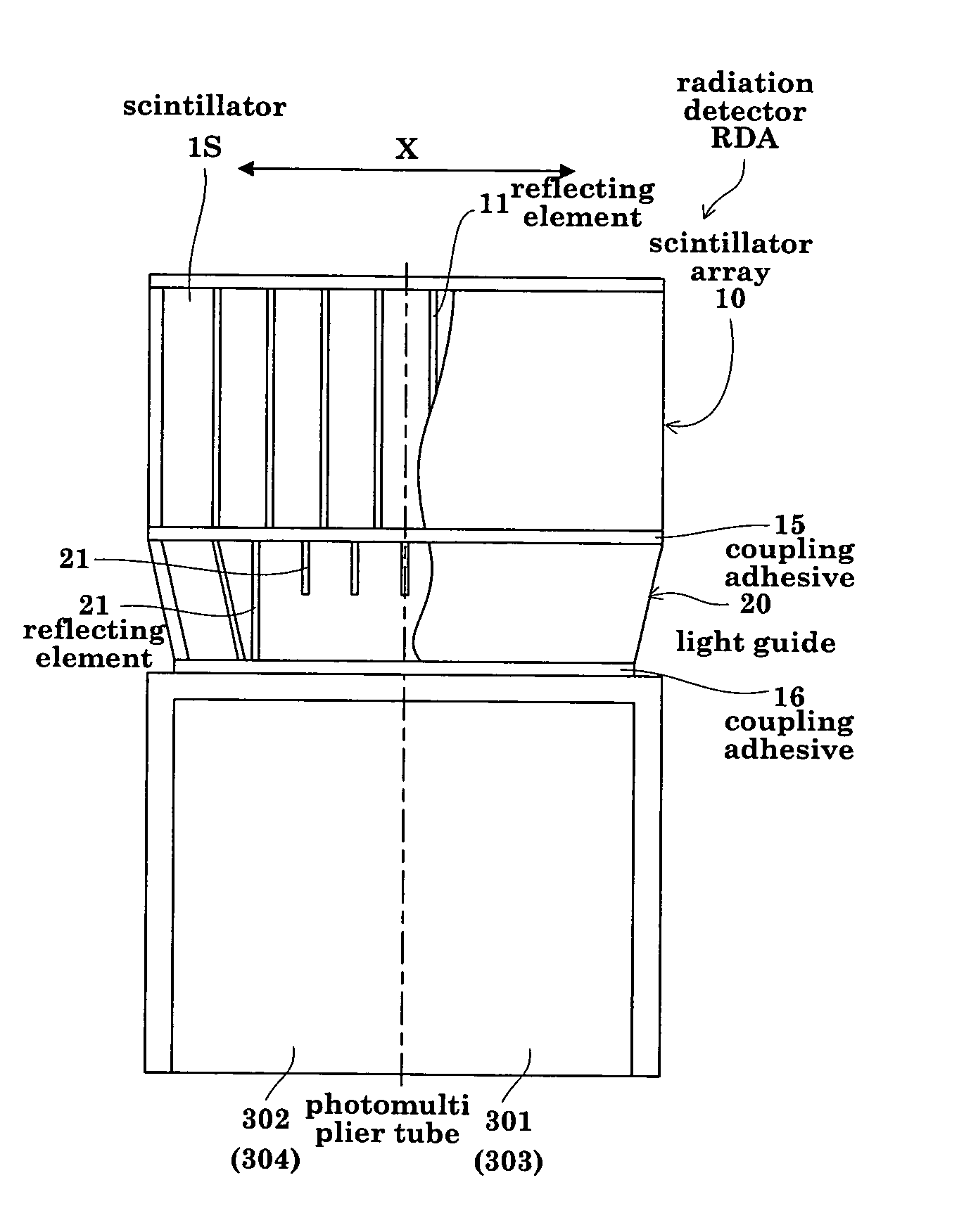
[0042]FIG. 3 is a view (side view) showing an outward appearance, in an X-direction seen from a Y-direction, of a radiation detector in one embodiment of this invention. FIG. 4 is a view (front view) showing an outward appearance, in the Y-direction seen from the X-direction, of the radiation detector;

[0043] The radiation detector RDA in this embodiment includes a scintillator array 10, a light guide 20 optically combined to the scintillator array 10, and four photomultiplier tubes 301, 302, 303 and 304 optically combined to the light guide 20. FIG. 3 shows the photomultiplier tube 301 and photomultiplier tube 302. FIG. 4 shows the photomultiplier tube 301 and photomultiplier tube 303.

[0044] The scintillator array 10 has scintillators 1S in a compact, two-dimensional arrangement, the scintillators 1S being defined by light reflecting elements 11 and light transmi...


PUM


Abstract

A scintillator array has a compact, two-dimensional arrangement of scintillators partitioned by light reflecting elements and light transmitting elements interposed between the scintillators. That is, the scintillator array has a lattice frame in the form of a crosswise combination of plate-like optical elements such as light reflecting elements and light transmitting elements. The lattice frame defines a plurality of cubicles. A transparent adhesive is poured into a rectangular vessel for receiving the lattice frame, the lattice frame is placed in the rectangular vessel, and then the scintillators are placed in the rectangular vessel. A cured resin object integrating the optical adhesive having cured, the lattice frame and the scintillators is removed from the vessel, and is contoured to make the scintillator array. In this way, the optical elements are arranged in the scintillator array without cutting them with a dicing saw or wire saw.

Description

BACKGROUND OF THE INVENTION [0001] (1) Field of the Invention [0002] This invention relates to a radiation detector having scintillators, a light guide and photomultiplier tubes arranged in the stated order and optically combined to one another, and to a method of manufacturing the radiation detector. [0003] (2) Description of the Related Art [0004] This type of radiation detector is used in a medical diagnostic apparatus such a PET (Positron Emission Tomography) apparatus or a SPECT (Single Photon Emission Computed Tomography) apparatus for detecting radiation (e.g. gamma rays) released from radioisotopes (RI) introduced into a patient and accumulated in a region of interest, and obtaining sectional images of RI distribution in the region of interest. The radiation detector includes scintillators that emit light in response to incident gamma rays released from the patient, and photomultiplier tubes for converting the light emitted from the scintillators to pulsed electric signals. ...

Claims


Application Information

Patent Timeline
Patent Type & Authority Applications(United States)
IPC IPC(8): G01T1/202G01T1/20H04N5/321
CPCG01T1/202
Inventor TONAMI, HIROMICHIOOI, JUNICHI
Owner SHIMADZU CORP
Why Eureka
Try Eureka