
Optimized particle distribution for slurry bubble column reactors

a technology of slurry bubble column and particle distribution, which is applied in the direction of instruments, oxygen compound purification/separation, chemical methods analysis, etc., can solve the problems of economic unattractive use, constrained gas and liquid flow parameters, and provide a fluidized bed

Inactive Publication Date: 2005-09-22
CONOCOPHILLIPS CO
View PDF3 Cites 12 Cited by
  • Summary
  • Abstract
  • Description
  • Claims
  • Application Information

AI Technical Summary

Benefits of technology

[0012] In another embodiment, the present invention provides a method for producing hydrocarbons from synthesis gas in a multiphase reactor. The method includes passing a synthesis gas feed stream over a catalyst in the multiphase reactor under reaction promoting conditions. The catalyst comprises both fresh catalyst particles and particles that may be partially or wholly deactivated and/or attritted. The...

Problems solved by technology

However, most natural gas is situated in areas that are geographically remote from population and industrial centers.
The costs of compression, transportation, and storage make its use economically unattractive.
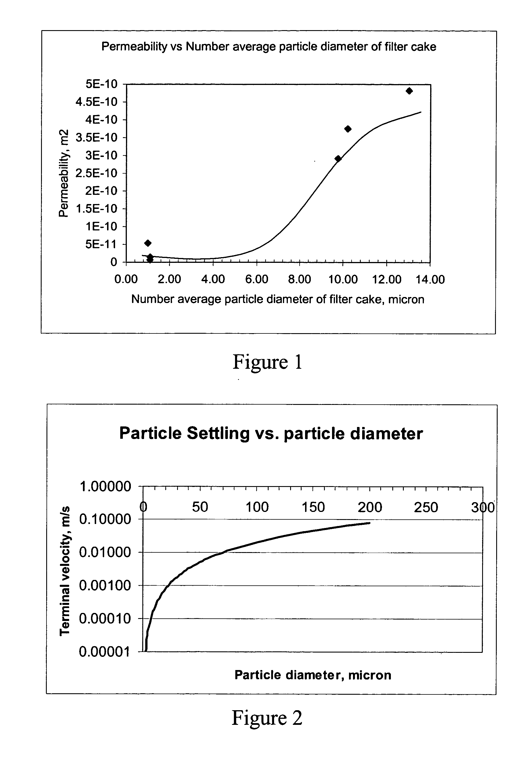
However, because larger particles tend to settle faster than smaller particles, it is more difficult to provide a fluidized bed, with the result that the gas and liquid flow parameters are constrained.
In slurry bubble column reactors where plug flow is desired, this results in a narrow window for the gas flow because it must be sufficient to generate enough liquid turbulence to distribute the catalyst particles but not so high that it results in a well-mixed flow regime.
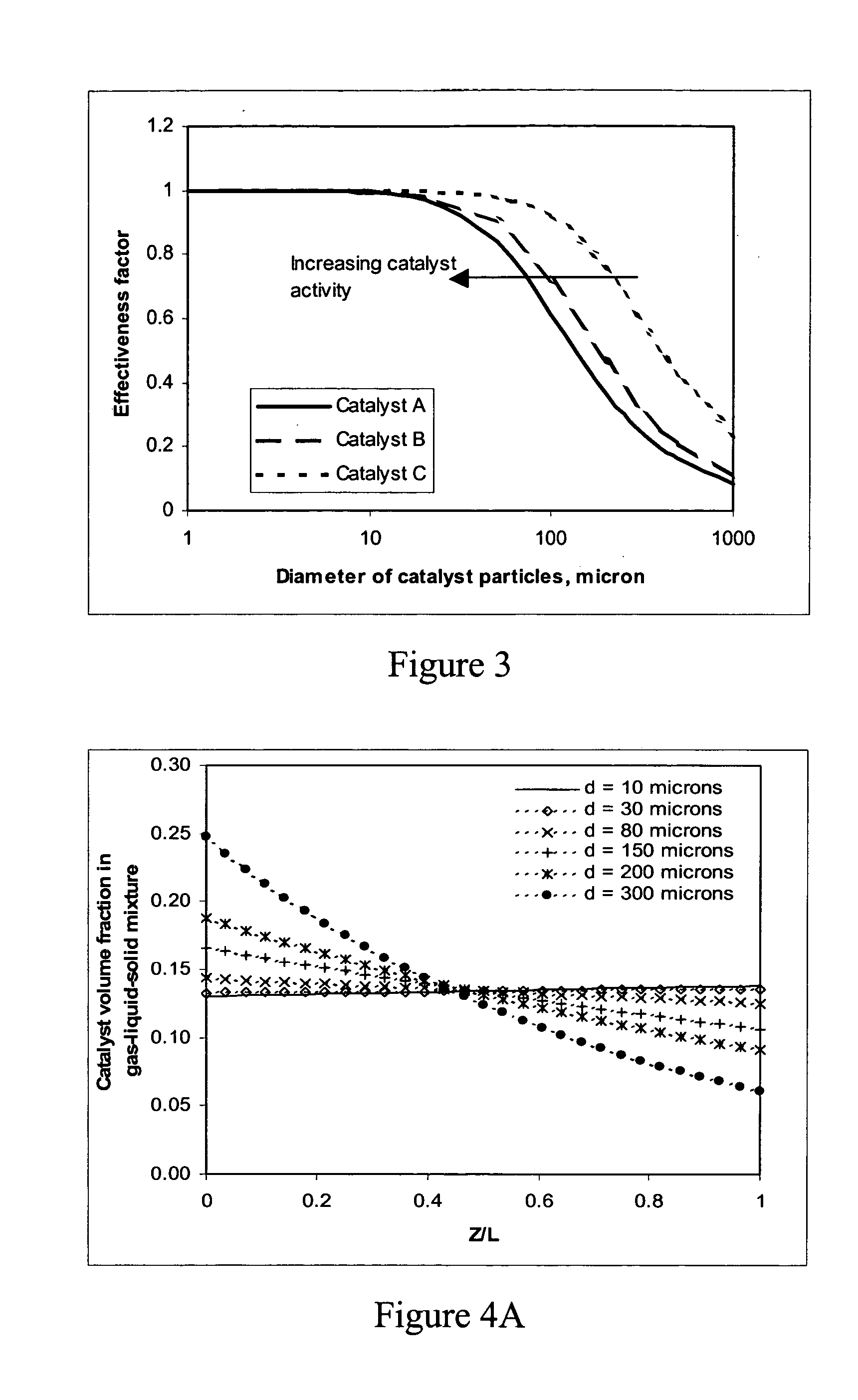
Such large particles are disadvantageous when used with the present catalysts because the activity of the present catalysts is such that their placement on large-diameter particles results in a reduction in the overall use of the catalyst.

Method used


Image

  • Optimized particle distribution for slurry bubble column reactors
  • Optimized particle distribution for slurry bubble column reactors
  • Optimized particle distribution for slurry bubble column reactors

Examples


Embodiment Construction

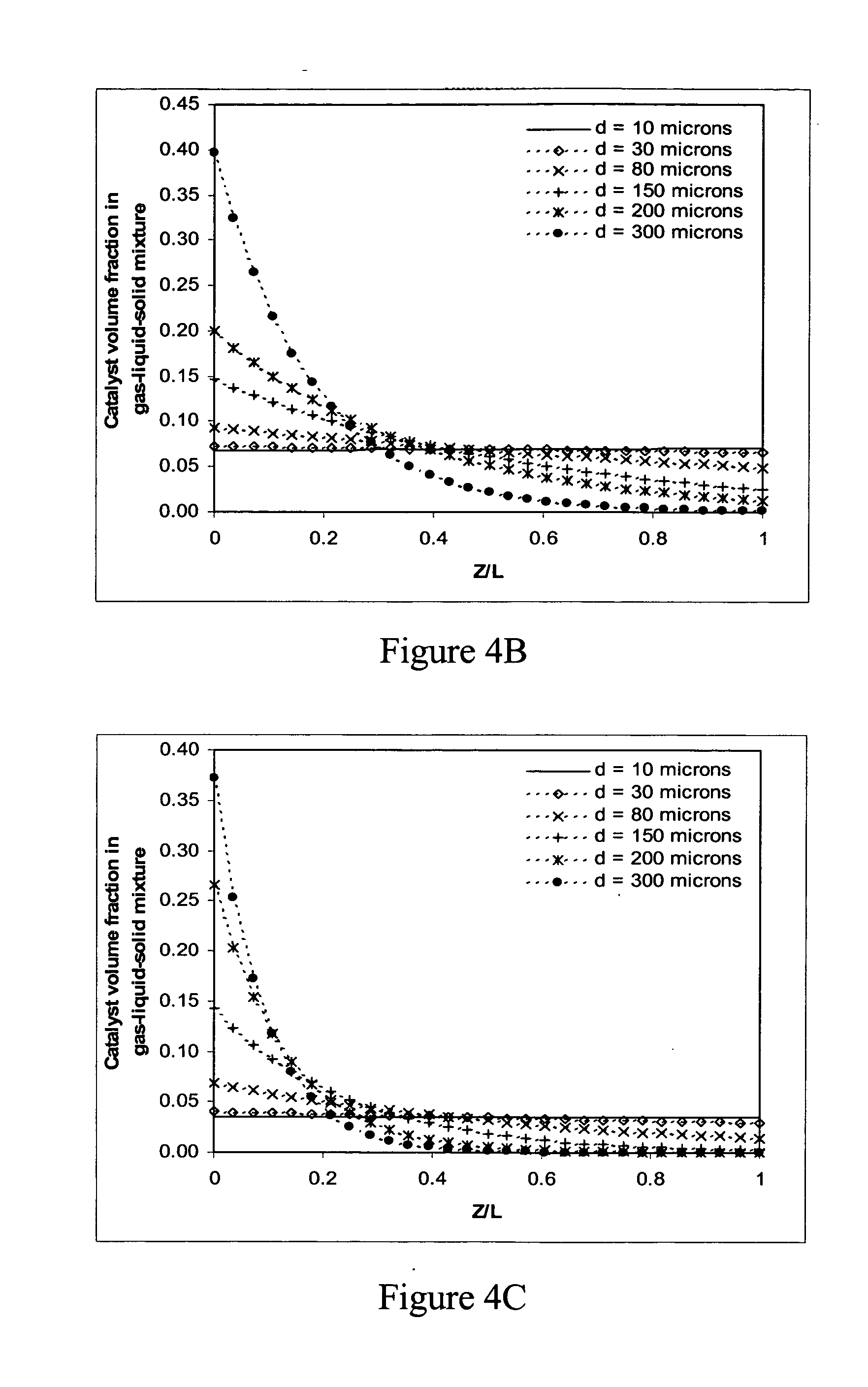
[0023] While much of the prior art has focused on maintaining catalyst particles in slurry bubble column reactors within a certain particle size range, the present invention provides more effective criteria for optimizing catalyst particle size for a given catalyst separation system, catalyst activity, and set of reactor operating conditions. In a preferred embodiment, the present invention provides a method for optimizing the operation of a slurry bubble column reactor. The method includes use of the dimensionless Archimedes number to calculate an optimum particle size range in a slurry bubble column reactor.

[0024] One preferred embodiment of the present invention is the Fischer-Tropsch synthesis of hydrocarbons using catalysts comprising a catalytically active metal, such as cobalt, iron, or ruthenium. The catalysts may contain a support, such as alumina, titania, zirconia, silica, or combinations thereof. Additionally, the catalyst may contain one or more promoters, comprising G...


PUM

PropertyMeasurementUnit
Fractionaaaaaaaaaa
Percent by massaaaaaaaaaa
Diameteraaaaaaaaaa

Abstract

A method for selecting maximum and minimum catalyst particle sizes for use in a multiphase reactor that reflects optimum operating conditions of the reactor is based on a maximum Archimedes number for estimating the maximum particle size and a property of a separation system linked to the reactor to determine the minimum particle size. The maximum Archimedes number could be selected based on a maximum catalyst non-uniformity in the reactor. Additionally, a method for producing hydrocarbons from syngas in a slurry bubble column reactor comprises the use of a plurality of fresh catalyst particles with an optimum size distribution based on a range of Archimedes numbers between about 0.02 and 250 or alternatively based on an average Reynolds number less than about 0.1.

Description

CROSS-REFERENCE TO RELATED APPLICATIONS [0001] Not applicable. STATEMENT REGARDING FEDERALLY SPONSORED RESEARCH OR DEVELOPMENT [0002] Not applicable. TECHNICAL FIELD OF THE INVENTION [0003] The present invention relates to a process for the preparation of hydrocarbons from synthesis gas—i.e., a mixture of carbon monoxide and hydrogen—typically labeled the Fischer-Tropsch process. More particularly, this invention relates to a method that provides for optimum design and operation of slurry bubble column reactors in a Fischer-Tropsch process. BACKGROUND [0004] Large quantities of methane, the main component of natural gas, are available in many areas of the world, and natural gas is predicted to outlast oil reserves by a significant margin. However, most natural gas is situated in areas that are geographically remote from population and industrial centers. The costs of compression, transportation, and storage make its use economically unattractive. To improve the economics of natural ...

Claims


Application Information

Patent Timeline
IPC IPC(8): B01J8/22C07C27/00C10G2/00G06F19/00
CPCB01J8/22B01J2208/00672C10G2/342C10G2/33B01J2208/00725
Inventor ESPINOZA, RAFAEL L.ODUEYUNGBO, OLUWASEYI A.ZHANG, JIANPINGMOHEDAS, SERGIO R.
Owner CONOCOPHILLIPS CO
Learn More