Eureka AIR delivers breakthrough ideas for toughest innovation challenges, trusted by R&D personnel around the world.

Inspection system and method for providing feedback

a technology of inspection system and feedback, applied in the direction of adaptive control, image enhancement, instruments, etc., can solve the problems of direct impact on the performance of the classifier, labor-intensive manual adjustment process, time-consuming and error-prone, etc., and achieve the effect of improving reliability and speed

Inactive Publication Date: 2005-09-22
AGILENT TECH INC
View PDF11 Cites 54 Cited by
  • Summary
  • Abstract
  • Description
  • Claims
  • Application Information

AI Technical Summary

Benefits of technology

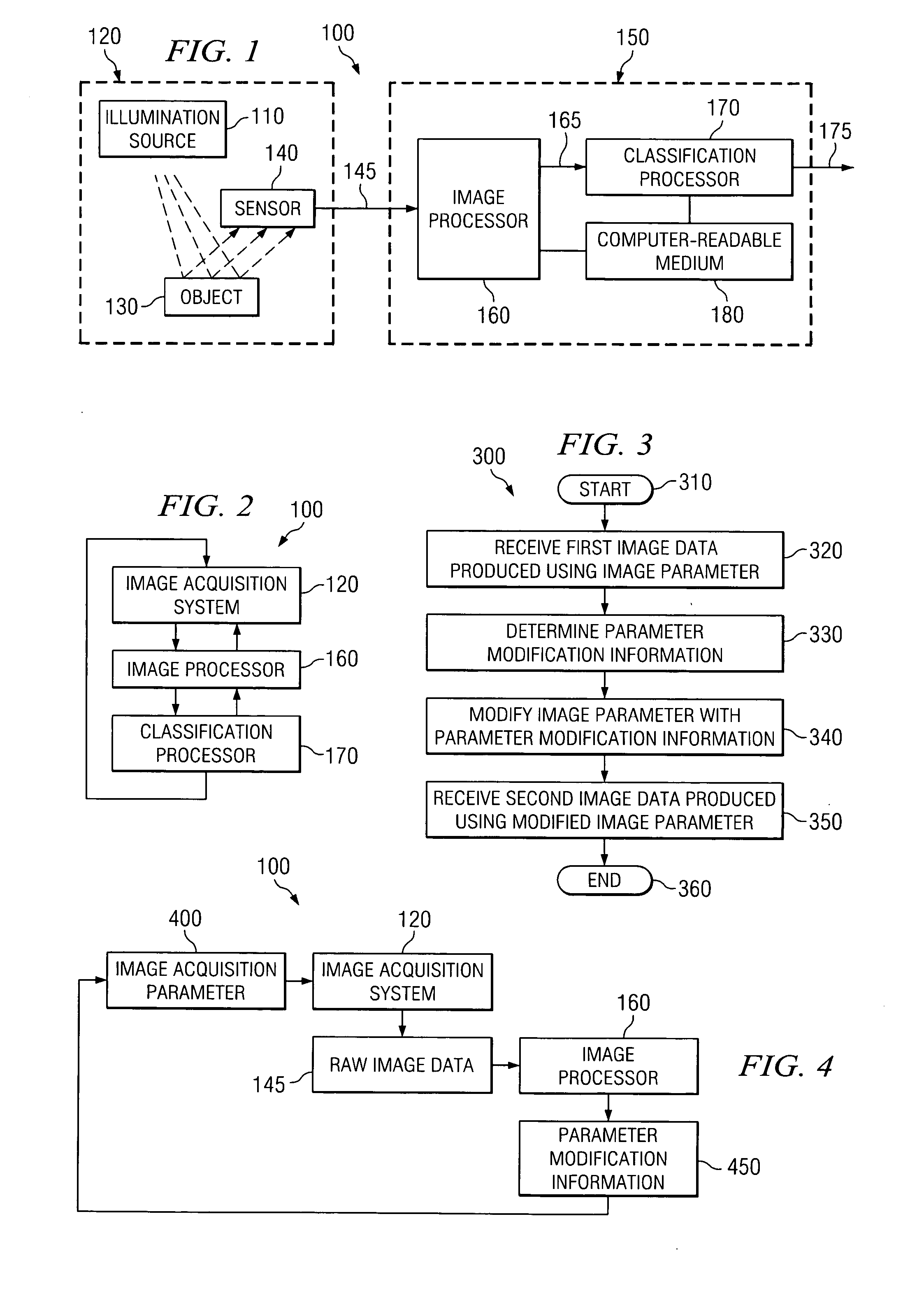
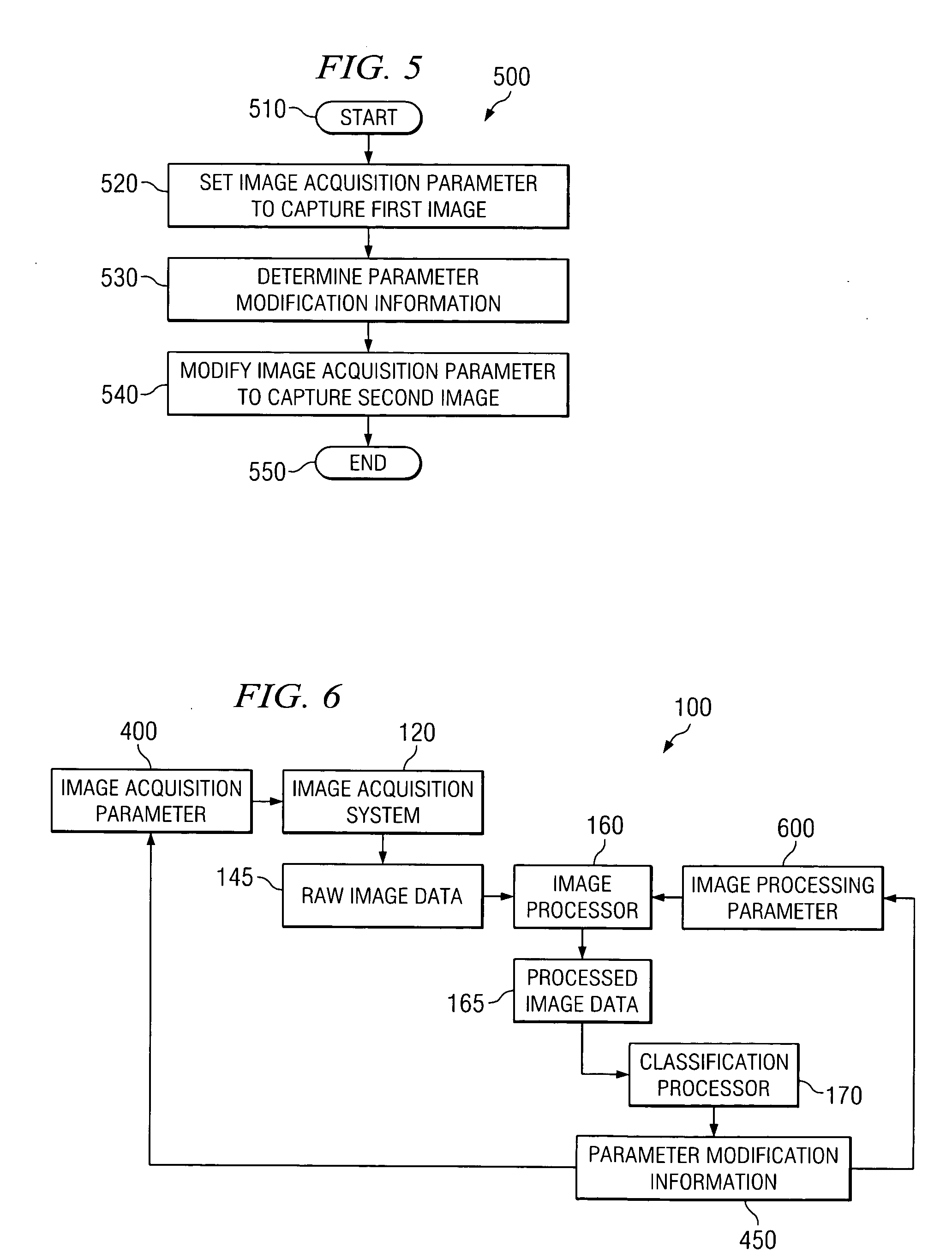
[0011] By providing feedback between the different parts of the inspection system, adjustments can be made automatically in real-time with improved reliability and increased speed. Furthermore, the invention provides embodiments with other features and advantages in addition to or in lieu of those discussed above. Many of these features and advantages are apparent from the description below with reference to the following drawings.

Problems solved by technology

However, the performance of the classifier is directly affected by the performance of the image acquisition system and the image processing system.
The manual adjustment process is labor-intensive, time consuming and error-prone.

Method used


Image

  • Inspection system and method for providing feedback
  • Inspection system and method for providing feedback
  • Inspection system and method for providing feedback

Examples


Embodiment Construction

[0025]FIG. 1 is a simplified illustration of an inspection system 100 capable of providing internal feedback to automatically make adjustments in real time. The inspection system 100 can be, for example, an automated printed circuit board inspection system, other manufacturing inspection system, luggage inspection system used in airport security or other type of inspection system. The inspection system 100 includes an image acquisition system 120 having an illumination source 110 for illuminating an object 130 and a sensor 140 including a plurality of pixels for capturing an image of the object 130 and producing raw image data 145 representing the image of the object 130. In one embodiment, the illumination source 110 is an X-ray source that produces a beam of X-rays and projects the X-ray beam through the object 130 to the sensor 140. In another embodiment, the illumination source 110 is a light source that emits light towards the object 130. The light is reflected off the surface ...


PUM


Abstract

An inspection system inspects features of an object using a feedback mechanism. The inspection system includes a processor that receives image data representing the object. The processor is operable to determine parameter modification information from the image data and modify an image parameter used during the production of the image data with the parameter modification information. The modified image parameter is used during the production of subsequent image data representing the object.

Description

CROSS-REFERENCE TO RELATED APPLICATIONS [0001] This application is related by subject matter to U.S. Utility Application for patent Ser. No. 10 / 699,542, entitled METHOD FOR CHOOSING TESTER DESIGNS AND USE MODEL USING OPERATING CHARACTERISTICS, filed on Oct. 31, 2003.BACKGROUND OF THE INVENTION [0002] 1. Technical Field of the Invention [0003] The present invention relates generally to the field of image acquisition inspection systems. More particularly, the present invention relates to adjustable image acquisition inspection systems using feedback mechanisms. [0004] 2. Description of Related Art [0005] Inspection systems are used in many different types of industries for a wide variety of purposes. For example, automated inspection systems are commonly employed in the manufacturing industry to inspect objects, such as solder joints and other components, on printed circuit boards (PCBs) for quality control purposes. In many automated inspection systems, the output is a classification...

Claims


Application Information

Patent Timeline
IPC IPC(8): G01N21/956G06K9/00G06K9/68G06T1/00G06T5/00G06T7/00
CPCG06T7/0004G06T2207/30152G06T2207/30141G05B13/00G05B6/00
Inventor CHOPRA, NASREENLI, JONATHAN QIANGBAHARAV, IZHAK
Owner AGILENT TECH INC
Why Eureka
Eureka Blog
Learn More