
Imaging stabilizer using micromirror array lens

Active Publication Date: 2005-09-22
STEREO DISPLAY
View PDF2 Cites 35 Cited by
  • Summary
  • Abstract
  • Description
  • Claims
  • Application Information

AI Technical Summary

Benefits of technology

[0017] The advantages of the present invention include elimination of need for mechanical macromotions to adjust the optical axis, high sampling rate, simple structure, and flexibility to use any type of vibration determination device.

Problems solved by technology

However, imaging devices with conventional vibration correcting devices have several problems as described below.
With increased complication and magnification, the vibration of the apparatus is a major factor in causing deterioration of the image quality.
Even a small vibration may results in large vibrations in the image due to the long focal length and the narrow view angle for high magnification.
However, the conventional optical vibration correcting devices still have several problems.
First, error in the correction of the picked-up image increases with an increase in the magnification of the image pickup lens.
Second, macro mechanical motions are required.
Third, they require complicated structures.
Fourth, they have very low sampling frequencies.
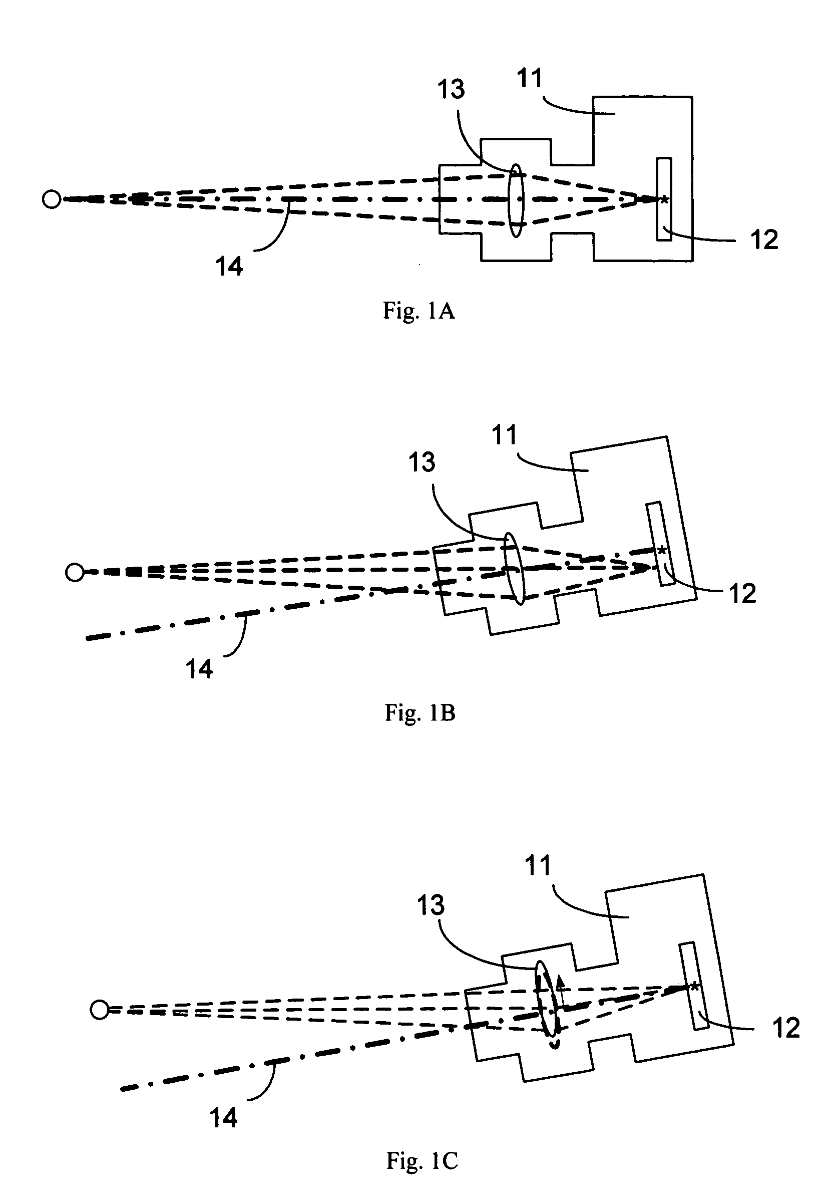
If there is vibration but it is not corrected, the tilt of optical axis results in the blurred image on the image sensor.

Method used


Image

  • Imaging stabilizer using micromirror array lens
  • Imaging stabilizer using micromirror array lens
  • Imaging stabilizer using micromirror array lens

Examples


Embodiment Construction

[0028] The present invention will now be described in detail with reference to a few embodiments thereof as illustrated in the accompanying drawings. In the following description, numerous specific details are set forth in order to provide a thorough understanding of the present invention. It will be apparent, however, to one skilled in the art, that the present invention may be practiced without some or all of these specific details. In other instances, well known process steps and / or structures have not been described in detail in order to not unnecessarily obscure the present invention.

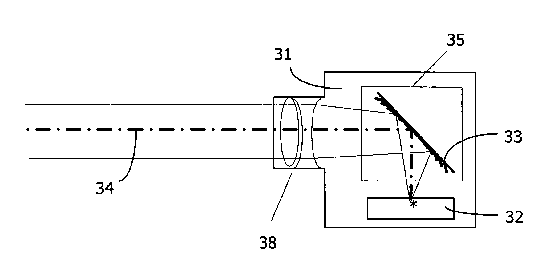
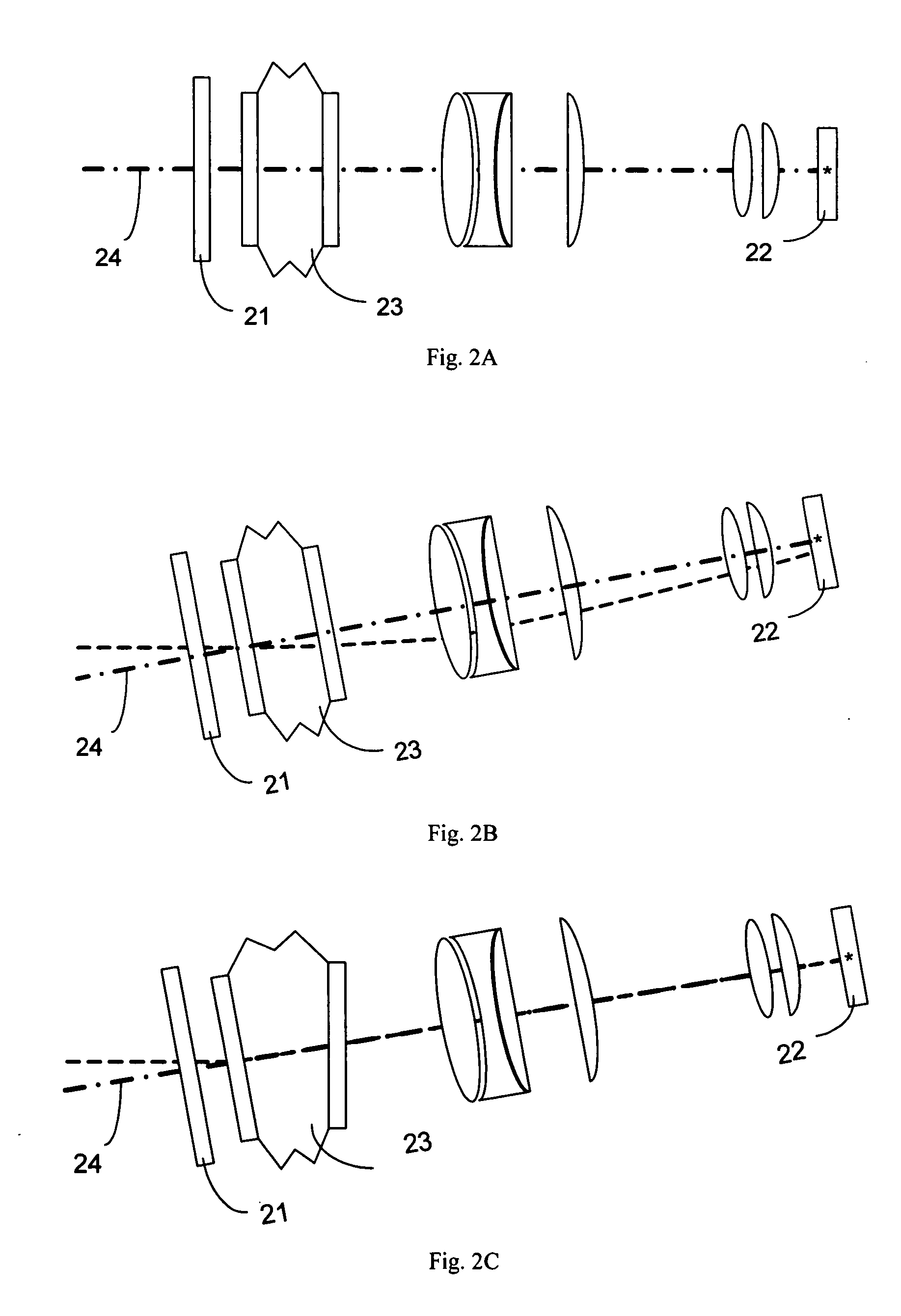
[0029] A vibration correction device (imaging stabilizer) using a micromirror array lens (MMAL) corrects for vibrations by controlling translations and rotations of mirrors to correct the tilt of the optical axis of the MMAL. Therefore, macromotions are not needed to change the direction of the optical axis of the MMAL, as described in U.S. patent application Ser. Nos. 10 / 855,715, 10 / 855,287, 10 / 8...


PUM


Abstract

A vibration correction device in an imaging device includes a micromirror array lens, configured to focus an object image onto an image sensor, and a vibration determination device, communicatively coupled to the micromirror array lens, configured to determine vibration of the imaging device and to generate a vibration correction signal. The micromirror array lens is adjusted to change its optical axis based at least in part on the vibration correction signal to correct for the vibration of the micromirror array lens. In one aspect, the micromirror array lens includes a plurality of micromirrors and the optical axis is changed by translation and / or rotation of the plurality of micromirrors. The advantages of the present invention include elimination of need for mechanical macromotions to adjust the optical axis, high sampling rate, simple structure, and flexibility to use any type of vibration determination device.

Description

REFERENCE TO RELATED APPLICATIONS [0001] This application is a continuation-in-part of, and claims priority to U.S. patent application Ser. No. 10 / 806,299 (Docket No. 1802.03), filed Mar. 23, 2004, U.S. patent application Ser. No. 10 / 822,414 (Docket No. 1802.04), filed Apr. 12, 2004, U.S. patent application Ser. No. 10 / 855,554 (Docket No. 1802.05), filed May 27, 2004, U.S. patent application Ser. No. 10 / 855,715 (Docket No. 1802.06), filed May 27, 2004, U.S. patent application Ser. No. 10 / 855,287 (Docket No. 1802.07), filed May 27, 2004, U.S. patent application Ser. No. 10 / 857,796 (Docket No. 1802.08), filed May 28, 2004, U.S. patent application Ser. No. 10 / 857,714 (Docket No. 1802.09), filed May 28, 2004, U.S. patent application Ser. No. 10 / 857,280 (Docket No. 1802.10), filed May 28, 2004, U.S. patent application Ser. No. 10 / 872,241 (Docket No. 1802.11), filed Jun. 18, 2004, U.S. patent application Ser. No. 10 / 893,039 (Docket No. 1802.12), filed Jul. 16, 2004, U.S. patent applicatio...

Claims


Application Information

Patent Timeline
IPC IPC(8): G02B27/64G03B17/00H04N5/225H04N5/228H04N5/232
CPCG02B27/648G03B5/06H04N5/23287H04N5/23248H04N5/2254H04N23/55H04N23/68H04N23/687
Inventor GIM, DONG WOOCHO, GYOUNG ILSEO, CHEONG SOO
Owner STEREO DISPLAY
Learn More