
Engine air-fuel control for an engine with valves that may be deactivated

a technology of air-fuel control and engine, which is applied in the direction of electric control, combustion engines, machines/engines, etc., can solve the problems of engine emissions may increase, reduce transient response performance, and conventional mechanical valve engines and electromechanically actuated valve engines may exhibit increased emissions, etc., to reduce undesirable influences, improve individual cylinder air-fuel detection and control, and prolong separation

Active Publication Date: 2005-09-22
FORD GLOBAL TECH LLC
View PDF99 Cites 50 Cited by
  • Summary
  • Abstract
  • Description
  • Claims
  • Application Information

AI Technical Summary

Benefits of technology

[0008] For example, by selectively adjusting electromechanical valve events in an internal combustion engine and then adjusting fuel or air at the active cylinders, individual cylinder air-fuel can be improved.
[0009] Engines with multiple cylinders may exhibit maldistribution for a number of reasons including but not limited to: varying port geometry between cylinders, electromechanical valve variation, injector location variation, port surface finish differences, and engine temperature variation between cylinders. These individual cylinder air-fuel variations are difficult to differentiate between cylinders because of manifold mixing, oxygen sensor response, and varying engine operating conditions. The inventors herein have reduced these undesirable influences and improved individual cylinder air-fuel detection and control by, in one example, extending the separation between adjacent cylinder exhaust intervals by control of electromechanical cylinder valves. For example, an eight-cylinder engine operating all eight cylinders has a 90° crank angle interval between individual cylinder events. Depending on exhaust manifold volume, engine speed, engine load, and other factors, a considerable amount of exhaust gas mixing may occur before the exhaust gas reaches an exhaust gas sensor. As a result, determining the air-fuel ratio of a single cylinder may be difficult. By increasing the interval between cylinder events, (e.g., deactivating four cylinders in an eight cylinder can increase the crank angle interval between cylinder events to 180°), mixing of exhausted gases from individual cylinders may be reduced since cylinder pressures have additional time to generate flow toward the atmosphere. By reducing exhaust gas mixing, individual cylinder air-fuel ratio control may be improved because past histories of adjacent cylinder combustion events may contribute a smaller fraction to the observed air-fuel ratio.
[0010] Further, the invention herein may be utilized in fuel saving cylinder modes. In these modes, an even greater concentration of the monitored cylinder air-fuel ratio may be observed. For example, combustion events occur every 180 degrees for a 4-cylinder, 4-stroke engine. When the same engine is operated in 2-cylinder mode, at the same torque, the cylinder charge mass increases, improving air-fuel detection at the confluence point, i.e., the point where cylinder exhaust combine and are detected by the oxygen sensor. In this example, air-fuel detection is improve by signal separation, since the number of crank angle degrees increases between cylinder events, and by increasing the cylinder mass fraction in the exhaust gas of the cylinder of interest.
[0011] In this way, improved individual cylinder air-fuel detection can be achieved thereby reducing engine emissions and improving transient response. Further, improved fuel economy can be achieved by accurately matching fuel and air charge amounts.

Problems solved by technology

Conventional mechanical valve engines and electromechanically actuated valve engines may exhibit increased emissions and reduced transient response performance if air-fuel maldistribution exists between cylinders.
Engine emissions may increase due to air-fuel mixtures that are too rich or too lean.
However, if a maldistribution of air-fuel exists between cylinders, one cylinder may produce a low hydrocarbon exhaust gas while another cylinder may misfire because of a leaner air-fuel mixture.
Further, during acceleration from idle, large rates of change in cylinder air amount may result in calculation errors that can produce air-fuel errors.
The air fuel errors may cause an engine to hesitate or stumble.
However, gas flow properties within an exhaust manifold are subject to engine operating conditions, i.e., mass flow rate, temperature, pressure amplitude, and pressure frequency.
Using weighting factors may not be sufficient to express each cylinder contribution at the confluence point under these conditions.
These individual cylinder air-fuel variations are difficult to differentiate between cylinders because of manifold mixing, oxygen sensor response, and varying engine operating conditions.
As a result, determining the air-fuel ratio of a single cylinder may be difficult.

Method used


Image

  • Engine air-fuel control for an engine with valves that may be deactivated
  • Engine air-fuel control for an engine with valves that may be deactivated
  • Engine air-fuel control for an engine with valves that may be deactivated

Examples


Embodiment Construction

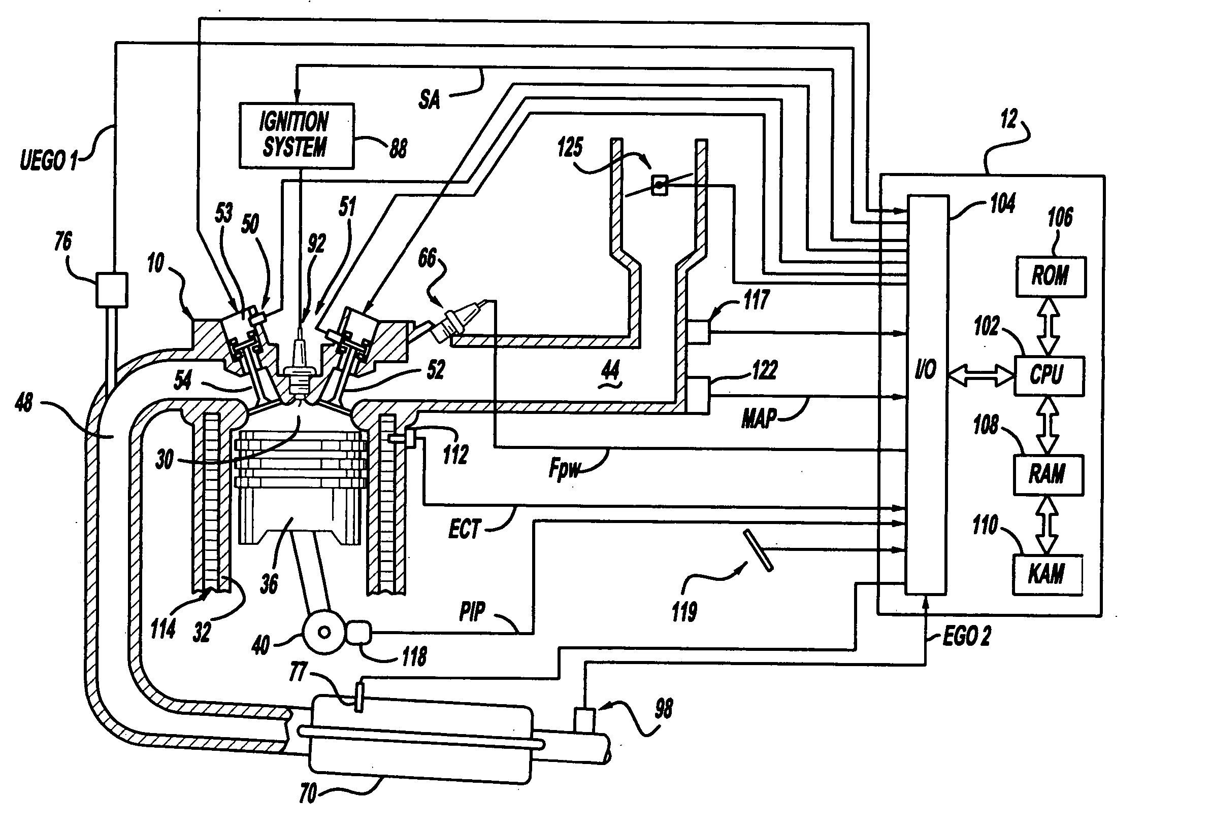
[0077] Referring to FIG. 1, internal combustion engine 10, comprising a plurality of cylinders, one cylinder of which is shown in FIG. 1, is controlled by electronic engine controller 12. Engine 10 includes combustion chamber 30 and cylinder walls 32 with piston 36 positioned therein and connected to crankshaft 40. Combustion chamber 30 is shown communicating with intake manifold 44 and exhaust manifold 48 via respective intake valve 52 an exhaust valve 54. Each intake and exhaust valve is operated by an electromechanically controlled valve coil and armature assembly 53. Armature temperature is determined by temperature sensor 51. Valve position is determined by position sensor 50. In an alternative example, each of valves actuators for valves 52 and 54 has a position sensor and a temperature sensor.

[0078] Intake manifold 44 is also shown having fuel injector 66 coupled thereto for delivering liquid fuel in proportion to the pulse width of signal FPW from controller 12. Fuel is del...


PUM


Abstract

A system and method to control engine valve timing to improve air-fuel control in an engine with valves that may be deactivated. Valves that may be deactivated are controlled in a manner to improve detection of individual cylinder air-fuel ratios.

Description

FIELD [0001] The present description relates to a method for controlling air-fuel ratio in an internal combustion engine and more particularly to a method for controlling valves that may be deactivated to improve engine air-fuel control. BACKGROUND AND SUMMARY [0002] Conventional mechanical valve engines and electromechanically actuated valve engines may exhibit increased emissions and reduced transient response performance if air-fuel maldistribution exists between cylinders. Engine emissions may increase due to air-fuel mixtures that are too rich or too lean. For example, during a cold engine start it is desirable to operate cylinders at a lean air-fuel mixture to reduce hydrocarbon emissions. However, if a maldistribution of air-fuel exists between cylinders, one cylinder may produce a low hydrocarbon exhaust gas while another cylinder may misfire because of a leaner air-fuel mixture. Further, during acceleration from idle, large rates of change in cylinder air amount may result ...

Claims


Application Information

Patent Timeline
Patent Type & Authority Applications(United States)
IPC IPC(8): F02D13/02F02D13/06F02D41/00F02D41/14F02D41/24F02D41/34F02D41/36
CPCF02D13/0207Y02T10/18F02D13/0257F02D13/06F02D41/0002F02D41/008F02D41/0082F02D41/0087F02D41/1454F02D41/2416F02D2013/0292F02D2041/0012F02D2200/1006F02D2250/18Y02T10/42F02D13/0253Y02T10/12Y02T10/40
Inventor GIBSON, ALEXKOLMANOVSKY, ILYA V.
Owner FORD GLOBAL TECH LLC
Learn More