
Dual-band antenna with an impedance transformer

Inactive Publication Date: 2005-09-15
HON HAI PRECISION IND CO LTD
View PDF5 Cites 26 Cited by
  • Summary
  • Abstract
  • Description
  • Claims
  • Application Information

AI Technical Summary

Benefits of technology

[0008] It is an object of the present invention to provide a dual-band antenna can be easily adjusted for impedance matching with its coaxial feed line.

Problems solved by technology

The external antenna protrudes a relatively long distance from the body of the mobile computer, which makes the computer aesthetically unpleasing and inconvenient to move.
In addition, the antenna is often bent, broken, knocked out of alignment or otherwise damaged because they can easily catch or strike objects such as people, walls, doors, etc.
Furthermore, the antenna requires a large support structure to secure the antenna to the housing of the computer and this support structure requires a considerable amount of space inside the body of the computer.
Although, the planar inverted-F antennas (PIFA) are structured so compact and lightweight, it can only operate in a single frequency band, which limits the use of this conventional antenna.
However, this means is limited by physical dimensions of connection strip and may influence the resonant frequencies of the antenna.

Method used


Image

  • Dual-band antenna with an impedance transformer
  • Dual-band antenna with an impedance transformer
  • Dual-band antenna with an impedance transformer

Examples


Embodiment Construction

[0020] Reference will now be made in detail to a preferred embodiment of the present invention.

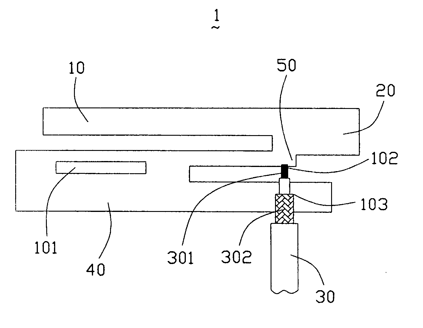
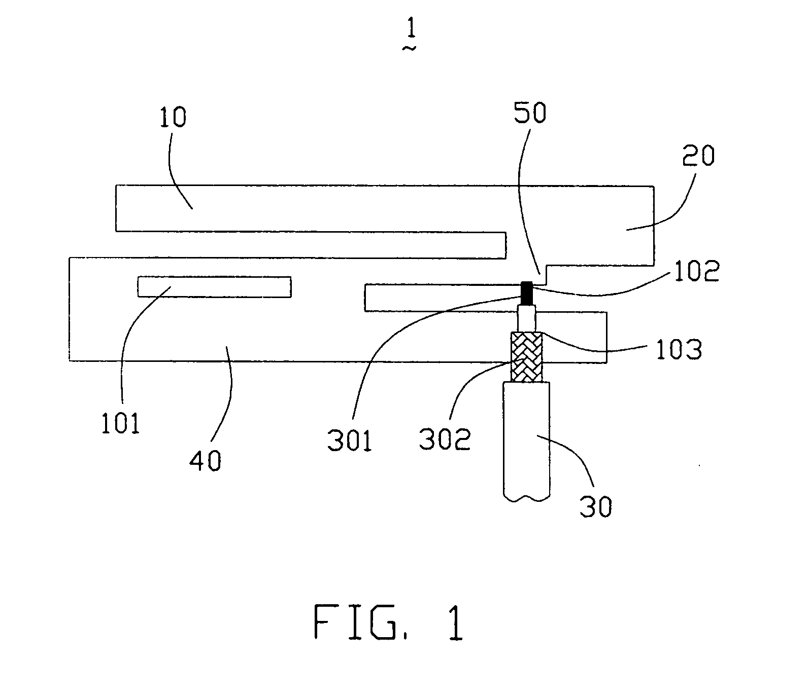
[0021] Referring to FIG. 1, a dual-band antenna 1 in accordance with a preferred embodiment of the present invention is formed of a planar metallic sheet, and includes a first and a second radiating element portions 10, 20 disposed at the horizontal direction, which are of different lengths and capable of being tuned to different frequency bands. The first radiating element portion 10 serves to generate a first (lower frequency) resonant frequency and the second radiating element portion 20 serves to generate a second (higher frequency) resonant frequency, wherein the length of the first radiating element portion 10 is selected to be ¼ wavelength of the central frequency of the first (lower frequency) resonant frequency, and that of the length of the second radiating element portion 20 is selected to be ¼ wavelength of the central frequency of the second (higher frequency) resonant freque...


PUM


Abstract

A dual-band antenna (1) for communication device includes a first radiating element portion (10) operating at a first frequency band, a second radiating element portion (20) operating at a second frequency band, an L-shaped ground portion (40), a conductive connection (50) interconnecting the first and second radiating element portions (10,20) with the ground portion (40) and a slot (101) served as an impedance transformer and positioned on the ground portion (40). The slot (101) is implemented as a capacitive load that eliminates the inductive part of the input impedance of the antenna, thereby the slot (101) can match the input impedance of the antenna with a feed line.

Description

BACKGROUND OF THE INVENTION [0001] 1. Field of the Invention [0002] The present invention relates generally to an antenna, and more particularly to a dual-band antenna for use with a wireless communication device. [0003] 2. Description of the Prior Art [0004] With the development of wireless communication technology, various products such as mobile computers for dual-band communication have high performance to meet the consumers'demands. Accordingly, if a mobile computer with wireless communication function desires to have high performance, it is critical for it to have a well-designed antenna, which having high gain, high directivity when required and characteristics that can be applied in dual frequency bands. [0005] Conventional antennas generally adapted to wireless communication products such as mobile computers are substantially grouped into two types, wherein one is external antenna and the other is internal antenna. The external antenna protrudes a relatively long distance f...

Claims


Application Information

Patent Timeline
IPC IPC(8): H01Q5/00H01Q5/364H01Q21/20
CPCH01Q5/364H01Q9/42
Inventor LIN, HSIEN-CHUTAI, LUNG SHENGHUNG, CHEN-TA
Owner HON HAI PRECISION IND CO LTD
Learn More