Encoder

Inactive Publication Date: 2005-09-15
KK TOKAI RIKA DENKI SEISAKUSHO
View PDF8 Cites 22 Cited by
  • Summary
  • Abstract
  • Description
  • Claims
  • Application Information

AI Technical Summary

Benefits of technology

[0004] It is an object of the present invention to provide an encoder that stably detects the movement amount of an object.
[0005] One aspect of the present invention is an encoder for detecting the amount of movement of a movable object having a plurality of slits. The encoder includes a light emitting device for emitting light toward the object so that the emitted light is passable through the slits of the object. A detector receives the emitted light of the light emitting device that passes through the slits and generates an ON signal when the amount of emitted light exceeds a threshold value. A current increasing circuit increases the amount of current flowing through the light emitting device when the detector generates the ON signal.

Problems solved by technology

However, in the prior art encoder, when the rotor plate stops rotating at a position in which the LED faces toward an edge of a slit (i.e., position in which the amount of light that passes through the slit is in the vicinity of the threshold value of the optical sensor), slight rotation of the rotor plate (unexpected rotation caused by external disturbances) may repetitively generate the ON and OFF signals.
Accordingly, the prior art rotor cannot stably detect the rotational angle (movement amount) of the rotor plate (object).

Method used


Image

  • Encoder
  • Encoder
  • Encoder

Examples


Embodiment Construction

[0010] An encoder 1 (rotational angle detector) according to a preferred embodiment of the present invention will now be described with reference to FIGS. 1 and 2. The encoder 1 detects the steering angle of a vehicle steering wheel.

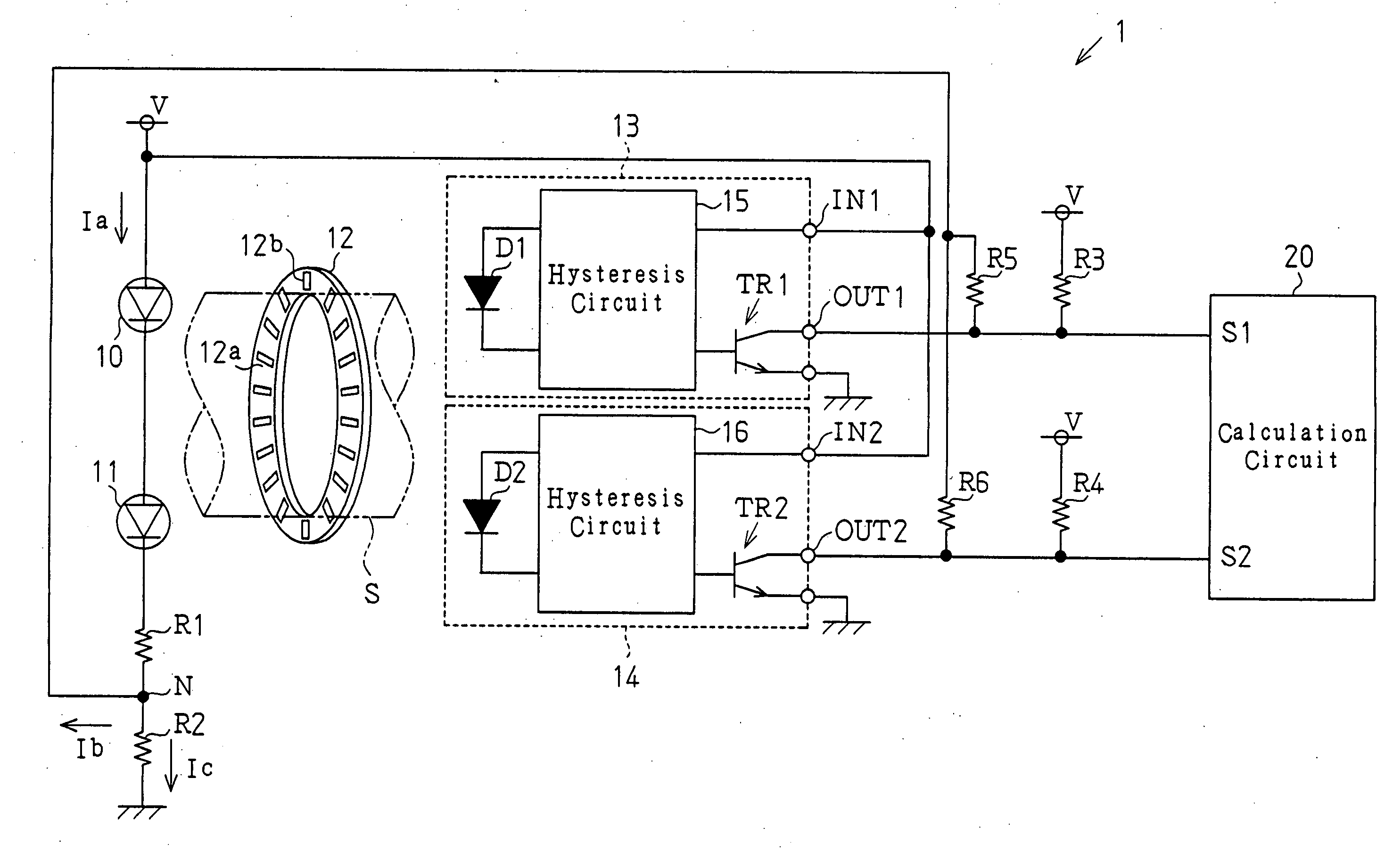
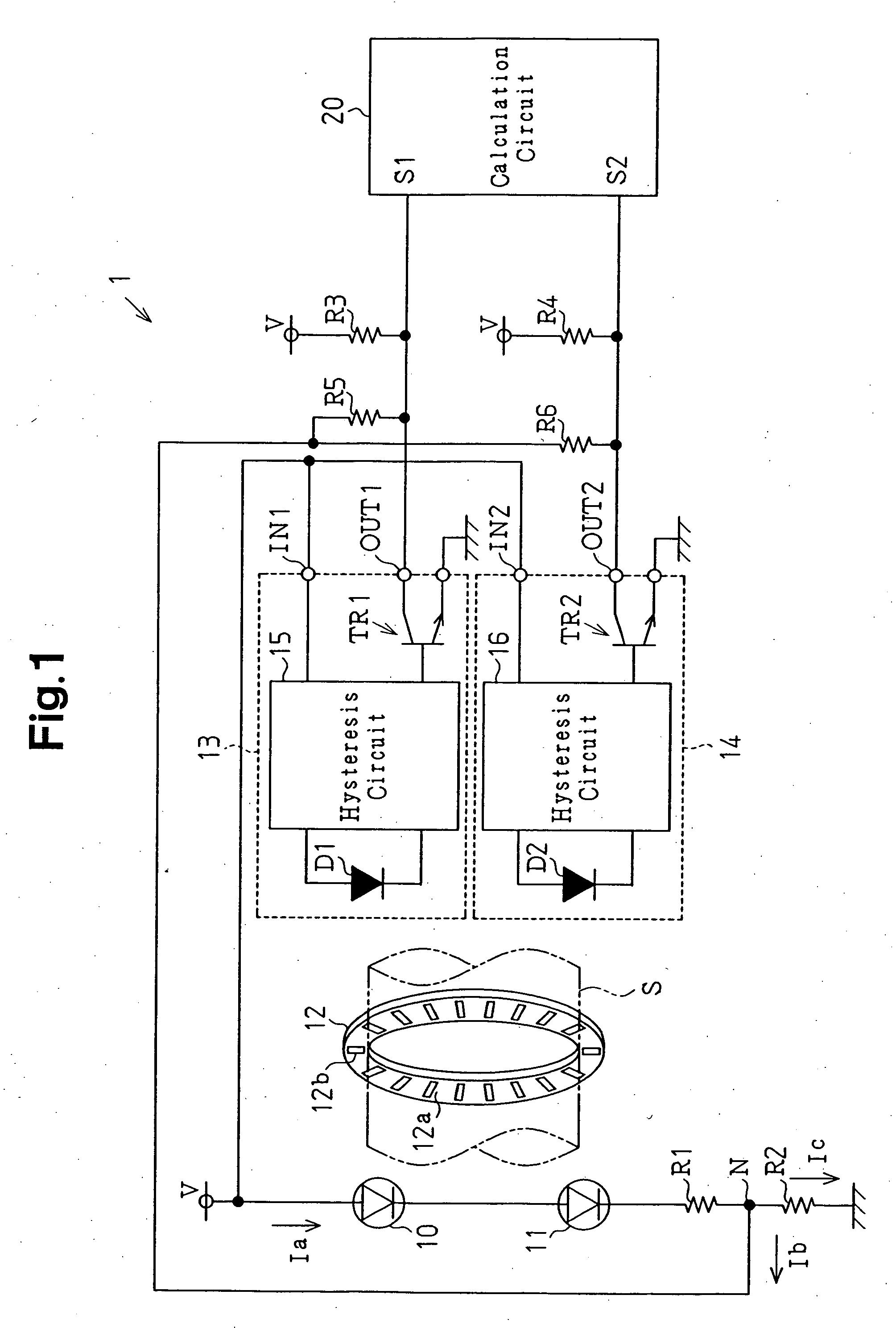
[0011] Referring to FIG. 1, the encoder 1 includes light emitting diodes (LEDs) 10 and 11 functioning as light emitting devices, a rotor plate 12, and optical sensors 13 and 14 arranged to sandwich the rotor plate 12 with the LEDs 10 and 11. The encoder 1 further includes a calculation circuit 20 for calculating the rotational angle of the rotor plate 12 using signals provided from the optical sensors 13 and 14. The encoder 1 may include three or more LEDs to form a failsafe configuration.

[0012] The rotor plate 12, which is annular and has a hole, includes a detection surface 12a. A steering shaft S is fitted in the hole of the rotor plate 12. A plurality of slits 12b are formed in the detection surface 12a of the rotor plate 12 at predetermined interv...


PUM


Abstract

An encoder for stably detecting the amount of movement of an object. The encoder includes an LED for emitting light toward a rotor plate including slits. An optical sensor generates an ON signal when the amount of emitted light passing through the slits exceeds a threshold value. A current increasing circuit increases the amount of current flowing through the LED when the optical sensor generates an ON signal.

Description

BACKGROUND OF THE INVENTION [0001] The present invention relates to an encoder for detecting the amount of movement of an object, and more particularly, to an encoder for detecting the steering angle of a vehicle steering wheel. [0002] An encoder that detects the rotational angle of a rotation body is known in the prior art. For example, Japanese Laid-Open Patent Publication No. 2002-98522 describes an encoder that detects the rotational angle of a rotor plate with a plurality of optical sensors. The encoder includes a light-emitting diode (LED), a rotor plate including a plurality of slits formed in the circumferential direction of the rotor plate, and an optical sensor arranged to sandwich the rotor plate with the LED. The optical sensor generates a signal corresponding to the amount of light that passes through the slits. More particularly, the optical sensor generates an ON signal when the amount of light is greater than a predetermined value and an OFF signal when the amount of...

Claims


Application Information

Patent Timeline
IPC IPC(8): G01D5/34G01D5/36
CPCG01D5/3473
Inventor SENGOKU, NORIMASAFUTAMURA, YASUHIKOITO, SHIGEJI
Owner KK TOKAI RIKA DENKI SEISAKUSHO
Why Eureka
Try Eureka