
Seat of vehicle

a seat and vehicle technology, applied in the field of seats of vehicles, can solve the problems of uncomfortableness for the occupant, difficult to sufficiently fit the side supporting blocks to the occupant, and difficulty in reducing the comfort of the occupant, and achieve the effect of restricting the movement of the occupan

Inactive Publication Date: 2010-05-04
HONDA MOTOR CO LTD
View PDF22 Cites 41 Cited by
  • Summary
  • Abstract
  • Description
  • Claims
  • Application Information

AI Technical Summary

Benefits of technology

[0013]Accordingly, while in the initial state where the expanding device is not in operation, the third supporting surfaces of the movable supporting blocks are maintained so as to be substantially flush with the first supporting surface of the center supporting block; therefore, it is possible to restrict the occupant having the relatively larger physique, from the both sides by the side supporting blocks, without causing the uncomfortableness to the occupant. Furthermore, when the expanding devices are operated from this state, the side supporting blocks will protrude and the third supporting surfaces of the movable supporting blocks will incline via the joining portions; therefore, the protruded side supporting blocks and the inclined movable supporting blocks can fittingly restrict from the both sides the occupant having the relatively smaller physique, without causing the uncomfortableness to the occupant due to applying excessive pressure or the like.
[0016]Accordingly, the pressing force from the expanding devices can be applied through the supporting plates onto the side supporting blocks and the movable supporting blocks in parallel manner. Therefore, the side supporting blocks and the movable supporting blocks can move smoothly and continuously while driving the expanding devices. Accordingly, the adjustment of the seat of a vehicle can be stably performed.
[0019]Accordingly, since the inclination angles of the movable supporting blocks centering on the fixing portions can be changed without moving the first supporting surface of the center supporting block, the adjustment of the seat of a vehicle can be stably performed without causing the uncomfortableness to the occupant due to the movement of the first supporting surface of the center supporting block.
[0021]According to the seat of a vehicle, while in an initial state where the expanding devices are not in operation, the amount of protrusions toward the inside in the width of the both side supporting blocks is the minimum. In this state, both of the side supporting blocks which are opened so as to have the maximum opening width will restrict the movement of the occupant having the relatively larger physique, from the both sides. Furthermore, when the expanding devices are operated from this state, the side supporting blocks will move to the inside in the width while maintaining the inclination angles of the side supporting blocks on the occupant-restriction side to the substantially constant angle, and thereby restricting the movement of the occupant from the both sides.
[0022]Accordingly, while in the initial state where the expanding devices are not in operation, the amount of protrusions toward the inside in the width of the both side supporting blocks is the minimum; therefore, it is possible to restrict the occupant having the relatively larger physique, from the both sides by the side supporting blocks, without causing the uncomfortableness to the occupant. On the other hand, when the expanding devices are operated, the side supporting blocks will protrude toward the inside in the width while maintaining the inclination angles of the side supporting blocks on the occupant-restricting side to be substantially constant, and thereby enabling fittingly restricting the sides of the occupant having relatively smaller physique, without causing the uncomfortableness to the occupant due to applying excessive pressure or the like.
[0025]Accordingly, the elastic members joining between the side supporting blocks and the seat frame member will permit the flexible movements of the side supporting blocks. And furthermore, the elastic members enable the side supporting blocks to easily return to the initial position.

Problems solved by technology

Therefore, there was a possibility of causing the uncomfortableness to the occupant.
In addition, in this conventional seat of a vehicle, it has been difficult to sufficiently fit the side supporting blocks to the occupant whose body sizes such as the shoulder width or the like is comparatively narrow.
On the other hand, in this conventional seat of a vehicle, there has been a possibility of causing the uncomfortableness to the occupant due to excessive restriction from the sides to the occupant whose body size comparatively wide.

Method used


Image

  • Seat of vehicle
  • Seat of vehicle
  • Seat of vehicle

Examples


first embodiment

A First Embodiment

[0042]A seat of a vehicle 1 of the present embodiment is a separated type seat on the driver's seat side or on the assistant driver's seat side.

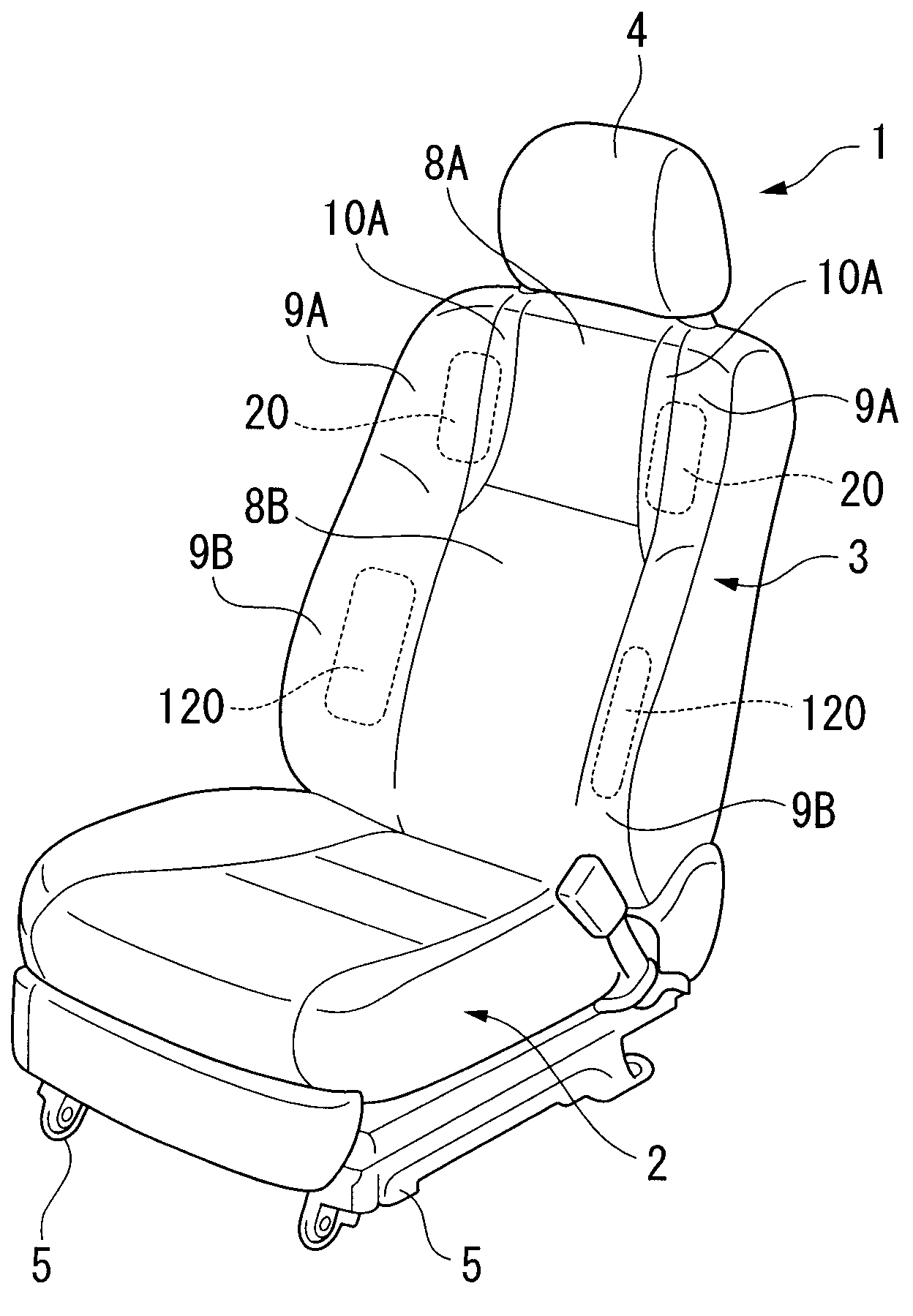
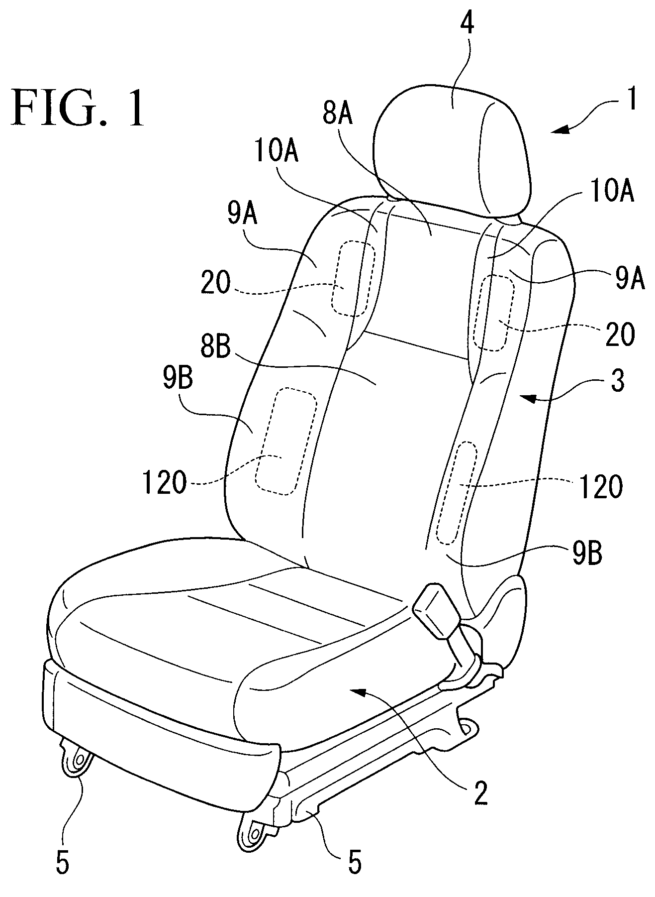
[0043]As shown in FIG. 1, a seat of a vehicle 1 is provided with a seat cushion 2 that supports from the hip to the thigh of an occupant, a seatback 3 that supports from the shoulder to the waist of the occupant, and a headrest 4 that supports the head of the occupant. The seat cushion 2 is installed in a vehicle body via seat rails 5 so as to be movable along the vehicle length. A lower end of the seatback 3 is joined with a back end of the seat cushion 2 via a hinge. The headrest 4 is attached to a top end of the seatback 3 such that the vertical position thereof is adjustable.

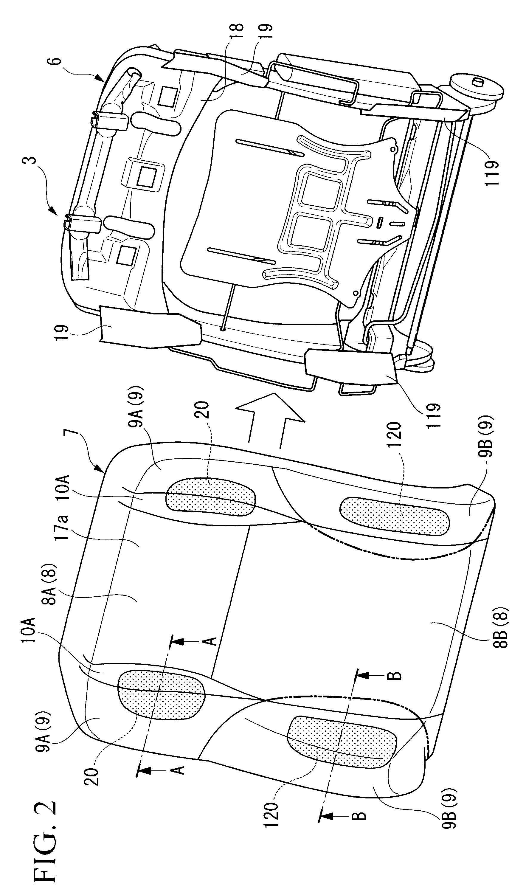
[0044]As shown in FIG. 2, the seatback 3 is provided with a substantially rectangular-shaped frame unit 6 including a metal frame panel 18 and spring members, and a cushion unit 7 that is attached to the front of the frame unit 6. The cushion unit 7...

second embodiment

[0068]Next, a seat of a vehicle according to a second embodiment of the present embodiment will be explained below with reference to FIG. 8. Moreover, in the following explanation, the differences with respect to the first embodiment will be mainly explained, and the explanations for the others are omitted here since they are the same as those of the first embodiment.

[0069]A seat of a vehicle 100 of the present invention is provided with a deformable cushion pad 150 that can change the length thereof, on a front end of the seat cushion 102, in addition to the bags 20 for holding the shoulders and the bags 120 for holding the hip.

[0070]This deformable cushion pad 150 is provided to the seat cushion 102 so as to be slidable in the length of the vehicle, and is movable in the forward and backward by expanding and shrinking a bag 151 arranged between the seat cushion 102 and the deformable cushion pad 150. Moreover, it may be arranged such that: non-illustrated occupant-detection sensor...


PUM


Abstract

This seat of a vehicle is provided with: a center supporting block having a first supporting surface for supporting an occupant; side supporting blocks that are arranged at both sides in the width of the center supporting block, and having a second supporting surface that more protrude than the first supporting surface of the center supporting block; movable supporting blocks each arranged between the center supporting block and the side supporting blocks, and each having a third supporting surface which is flush with the first supporting surface while in an initial state; joining portions each joining between the side supporting blocks and the movable supporting block; and expanding devices that are arranged at a back side of the side supporting blocks, expand the side supporting blocks, and incline the movable supporting blocks with respect to the first supporting surface of the center supporting block.

Description

[0001]Priority is claimed on Japanese Patent Application No. 2006-333418, filed Dec. 11, 2006, the contents of which are incorporated herein by reference.BACKGROUND OF THE INVENTION[0002]1. Field of the Invention[0003]The present invention relates to a seat of a vehicle that can change the shapes and the attitudes thereof in accordance with the physique of an occupant.[0004]2. Description of the Related Art[0005]A conventional seat of a vehicle is proposed which is provided with a seatback and a seat cushion each having side supporting blocks for supporting the sides of an occupant (for example, Japanese Examined Utility Model Application, Second Publication No. H03-8118).[0006]This seat of a vehicle is provided with the side supporting blocks that protrude more forward than a supporting surface of a center supporting block that supports the occupant, at both sides of the center supporting block. These side supporting blocks support the sides of the shoulders, the hip, the thighs, a...

Claims


Application Information

Patent Timeline
Patent Type & Authority Patents(United States)
IPC IPC(8): A47C7/14
CPCB60N2/449B60N2/4415B60N2/914B60N2/99
Inventor KAYUMI, TETSUYAYOKOYAMA, SADAHIROHASHIMOTO, KANEAKI
Owner HONDA MOTOR CO LTD
Learn More