
Cutting unit

Inactive Publication Date: 2005-09-15
PURPLE COWS
View PDF17 Cites 12 Cited by
  • Summary
  • Abstract
  • Description
  • Claims
  • Application Information

AI Technical Summary

Benefits of technology

[0007] According to the present invention, this object is achieved in that there is provided, preferably on a different side of the bed, a rotary cutting device that has a knife carriage displaceable on a guide bar and a circular knife rotatably mounted therein. The basic idea of the invention is thus to make available a cutting unit having two different kinds of cutting device, the one cutting device having strengths in the area in which the other cutting device works less well. Whereas the guillotine cutting device is suitable in particular for trimming sheet stacks, the rotary cutting device according to the present invention is characterized by a clean cut even with minimal excess lengths or when cutting off margins. It can therefore be used particularly effectively for trimming the margins of photographic prints or the like. The cutting unit according to the present invention is thus substantially more versatile to use, and takes up no more space than known cutting units of the species.
[0010] According to a further feature of the invention, provision is made for the guide bar to be raisable from a lower cutting position into an upper initial position, and lowerable from the latter back into the cutting position; and for the gap between bed and guide bar to be inaccessible from the ends of the guide bar. The idea underlying this is to effect the vertical movement of the circular knife not by way of the knife carriage but by means of the guide bar, by first raising the guide bar in order to slide the sheet stock through and then lowering it into the cutting position in which the circular knife rests on the bed. This makes handling of the cutting operation substantially simpler, and results in clean cuts. It is particularly important in this context that the gap between guide bar and bed be inaccessible from the ends of the guide bar, i.e. be covered there, so that it is not possible for the operator's fingers to enter the gap in that region and get caught as the guide bar is lowered.
[0012] The guide bar can be suspended in such a way that without actuation, it assumes the cutting position in which the circular knife rests on the bed. The guide bar can be raised manually in order to slide the sheet material through the gap between guide bar and bed. As an alternative to this, however, the possibility also exists that without actuation, the guide bar is held in the initial position by means of a spring. This facilitates sliding of the sheet material through the gap, but requires that the guide bar be pushed down for the cutting operation. A clean cut is obtained with this embodiment as well, however, since the guide bar can be pushed down with one hand and the knife carriage displaced with the other hand; this is much simpler in terms of handling than with known rotary cutting devices, in which the knife carriage must be pushed down and simultaneously displaced.
[0016] The invention further provides that the guillotine cutting device is exchangeable for the rotary cutting device and vice versa. The bed can, in this fashion, be equipped alternately with the cutting device that is especially suitable for that particular cutting operation. If, for example, a sheet material made up of several plies of paper or film is to be trimmed, the guillotine cutting device is joined to the bed. If individual photographs or the like are to be trimmed, the guillotine cutting device is replaced with the rotary cutting device, since it is particularly suitable therefor. The advantage of exchangeability as compared with a fixed arrangement of both cutting devices is the fact that the one cutting device does not interfere with placement of the sheet material when trimming with the other cutting device. This also makes it possible to keep the bed relatively short in the direction transverse to the longitudinal axis of the respective cutting device, and thus to make the cutting unit compact and thus also easy to transport.
[0018] Lastly, provision is made according to the invention for the bed to comprise an additional bed that can be pulled out and retracted transversely to the longitudinal axis of the guillotine or rotary cutting device. The bed can thereby be made substantially longer for trimming larger formats. For smaller formats and for transporting the cutting unit, the additional bed can be retracted into the main bed so that the cutting unit requires only a small amount of space.

Problems solved by technology

Sheet material can be cut relatively well with such cutting units if the sheet material projects not inconsiderably beyond the counterknife, since otherwise the risk exists that the excess length will be pushed downward by the blade and not trimmed cleanly.
Difficulties are encountered in producing a smooth cut edge if, in particular, there is only a small excess length beyond the counterknife.
With guillotine cutting devices the risk also exists that the bearing assembly of the knife arm may acquire play over time, so that in order to produce a smooth cut it is necessary to press the knife arm with considerable pressure against the counterknife.
Since this condition of the cutting unit is not detectable, unsatisfactory cutting results are obtained.

Method used


Image

  • Cutting unit
  • Cutting unit
  • Cutting unit

Examples


Embodiment Construction

)

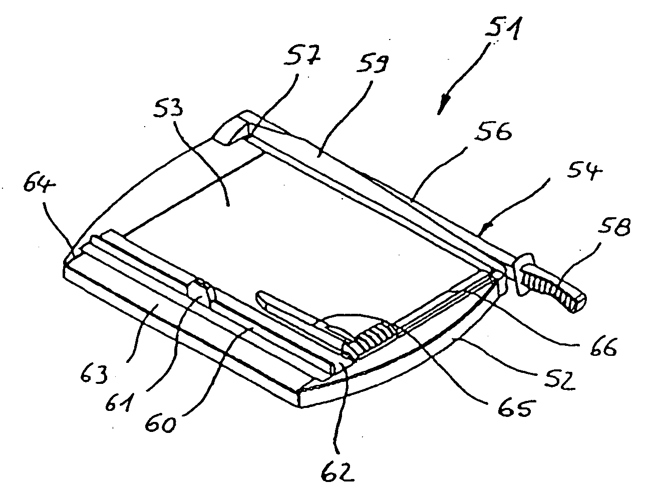
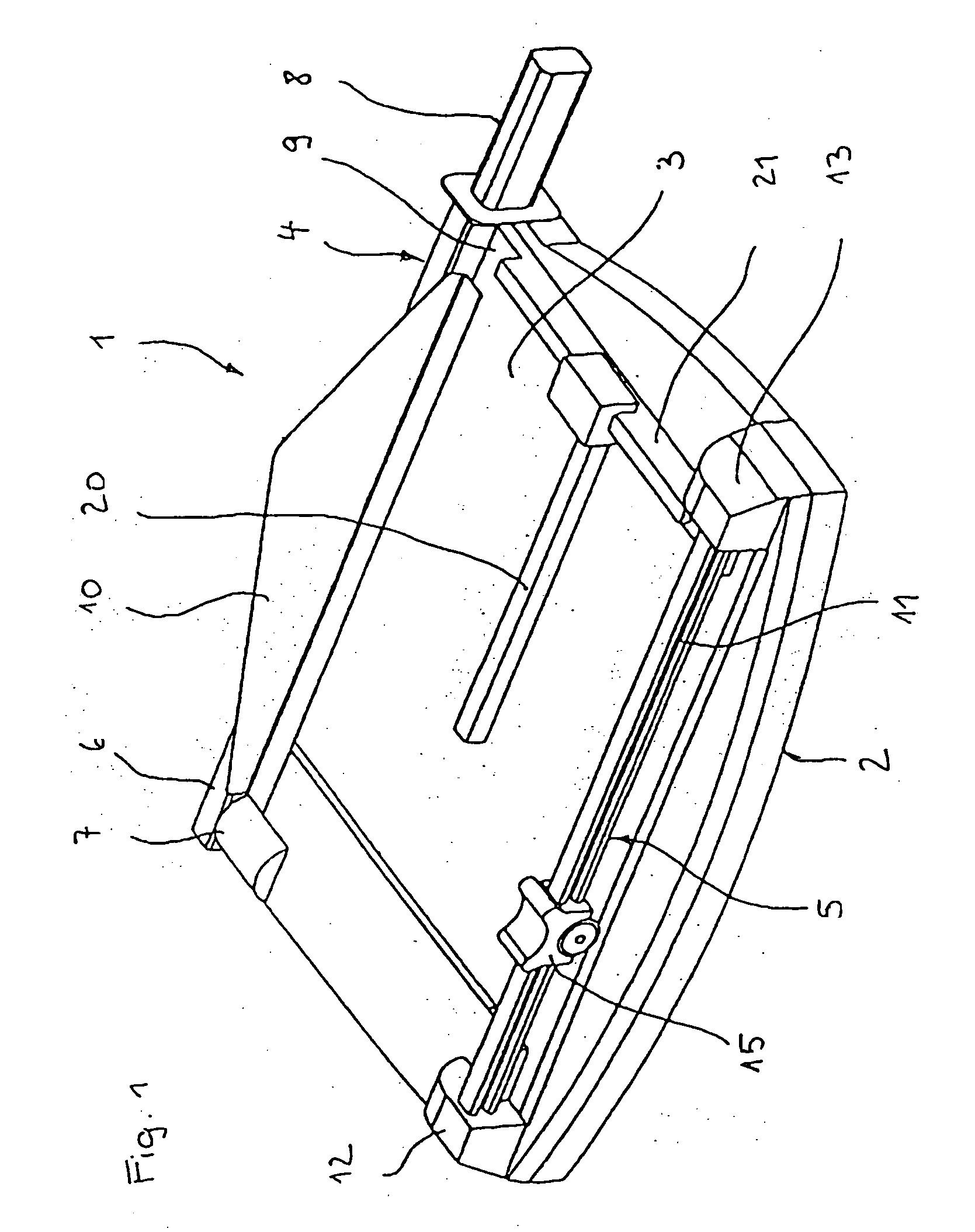
[0030] Cutting unit 1 depicted in FIG. 1 comprises a frame plate 2, substantially rectangular in plan, whose horizontal upper side forms a bed 3 for sheet material to be trimmed. A guillotine cutting device 4 is arranged on the upper (in this view) longitudinal side, and a rotary cutting device 5 on the lower (in this view) longitudinal side.

[0031] Guillotine cutting device 4 comprises a knife arm 6 that is mounted pivotably, in a bearing 7, about a horizontal axis extending transversely to the longitudinal side there. Knife arm 6 is equipped on its lower side, substantially over its entire length, with a cutting knife that is concealed in this view. Configured at the free end of knife arm 6 is a handle 8 with which knife arm 6 can be pivoted upward and downward. In the position shown, knife arm 6 is located in the lower terminal position.

[0032] The cutting knife of knife arm 6 corresponds to a counterknife 9 that is recessed flush into bed 3. Joined to knife arm 6 is a protectiv...


PUM

PropertyMeasurementUnit
Lengthaaaaaaaaaa
Angleaaaaaaaaaa
Flexibilityaaaaaaaaaa

Abstract

A cutting unit (1, 31, 47, 51) for trimming sheet material (18, 44) such as paper or films, comprises a planar bed (3, 33, 53) for supporting the sheet material (18, 44). A bed is equipped on one side with a guillotine cutting device (4, 54) that has a pivotably mounted knife arm (6, 56) having a blade held thereon and a counterknife (9) held in stationary fashion on the bed (3, 33, 53). There is additionally provided a rotary cutting device (5, 35, 55) that has a knife carriage (14, 36, 61) displaceable on a guide bar (11, 35, 60) and a circular knife (15, 39) rotatably mounted thereon.

Description

CROSS-REFERENCE TO RELATED APPLICATIONS AND CLAIM TO PRIORITY [0001] This is a continuation in part of application Ser. No. 10 / 797,024, filed Mar. 11, 2004, priority to which is claimed under 35 U.S.C. § 120, the disclosure of which is incorporated herein by reference. This application is based upon application number 04 009 250.4, filed Apr. 20, 2004 in the European Patent Office, the disclosure of which is incorporated herein by reference and priority to which is claimed under 35 U.S.C. § 119.FIELD OF THE INVENTION [0002] The invention concerns a cutting unit for trimming sheet material such as paper, films or the like, having a planar bed for supporting the sheet material, which bed is equipped on one side with a guillotine cutting device that has a pivotably mounted knife arm having a blade held thereon and a counterknife held in stationary fashion on the bed. BACKGROUND OF THE INVENTION [0003] Cutting units of the aforesaid kind are provided in particular for office use. They s...

Claims


Application Information

Patent Timeline
IPC IPC(8): B26D1/18
CPCB26D1/185B26D9/00B26D1/30Y10T83/8822Y10T83/7684Y10T83/929Y10T83/8812Y10T83/7763
Inventor LOIBL, BERND
Owner PURPLE COWS
Learn More