Vacuum apparatus and transfer apparatus

a transfer apparatus and vacuum technology, applied in the field of vacuum apparatus and transfer apparatus, can solve the problems of increasing rigidity for receiving load, hard to bend tape, etc., and achieve the effects of reducing the area of the transfer chamber, reducing the rigidity of the receiving load, and increasing the stability of the supporting hand of the workpiece holder

Inactive Publication Date: 2005-03-22
SEIKO INSTR INC
View PDF12 Cites 8 Cited by
  • Summary
  • Abstract
  • Description
  • Claims
  • Application Information

AI Technical Summary

Benefits of technology

If the tape is symmetrically provided as a pair and both tip end portions of this pair of transfer tapes are provided with one work-piece holder hand, the transfer and supporting of the work-piece holder hand becomes further stable.
If a tape accommodating cylinder is provided downward the transfer chamber and the rear end side of the transfer tape is accommodated inside this case, it becomes possible to make the area of the transfer chamber smaller.
When using the tape accommodating cylinder, magnets are provided in the inside and the outside of this tape accommodating cylinder. By making the magnet of the inside follow movement of the magnet of the outside, it becomes possible to move the tape from the outside of the vacuum apparatus.
Also, further, if the work-piece holder hand is attached to a tip member of a linear guide portion attached to a base of the transfer apparatus, supporting of the work-piece holder hand becomes further stable.
If this linear guide portion has a plurality of slide portions between the base and the tip member, it becomes possible to make a moving distance of the work-piece holder hand longer.
If a plurality of the holder hands for the work-piece are provided in the transfer apparatus and this plurality of holder hands for the work-piece are disposed in an upper side and a lower side, it becomes possible to perform transfer to and transfer from of the work-piece with one opening / closing operation of the gate valve.

Problems solved by technology

If the thickness direction of the transfer tape is made to be perpendicular, the rigidity for receiving load increases and the tape becomes hard to be bent.

Method used


Image

  • Vacuum apparatus and transfer apparatus
  • Vacuum apparatus and transfer apparatus
  • Vacuum apparatus and transfer apparatus

Examples


first embodiment

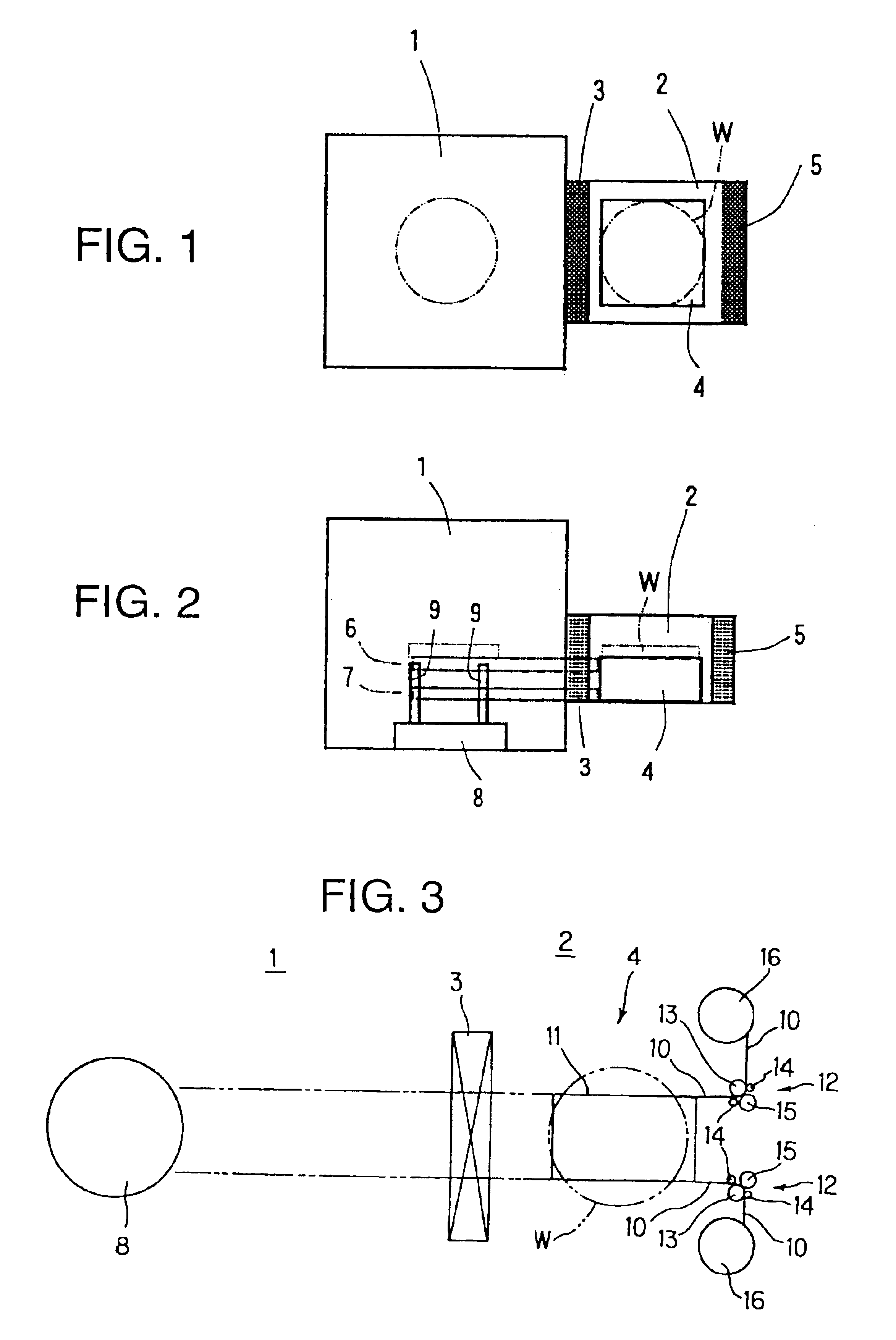
FIG. 1 is a diagram for explaining a construction of a vacuum apparatus in accordance with the First embodiment of the present invention. Reference numeral 1 indicates a process chamber for processing a work-piece (a wafer in this embodiment) W such as by CVD. Reference numeral 2 indicates a transfer chamber connected to the process chamber 1 via a gate valve 3. A transfer apparatus 4 is set in this transfer chamber 2. Also, a blocking door 5 for loading / unloading the work-piece is provided between the transfer chamber 2 and the outside.

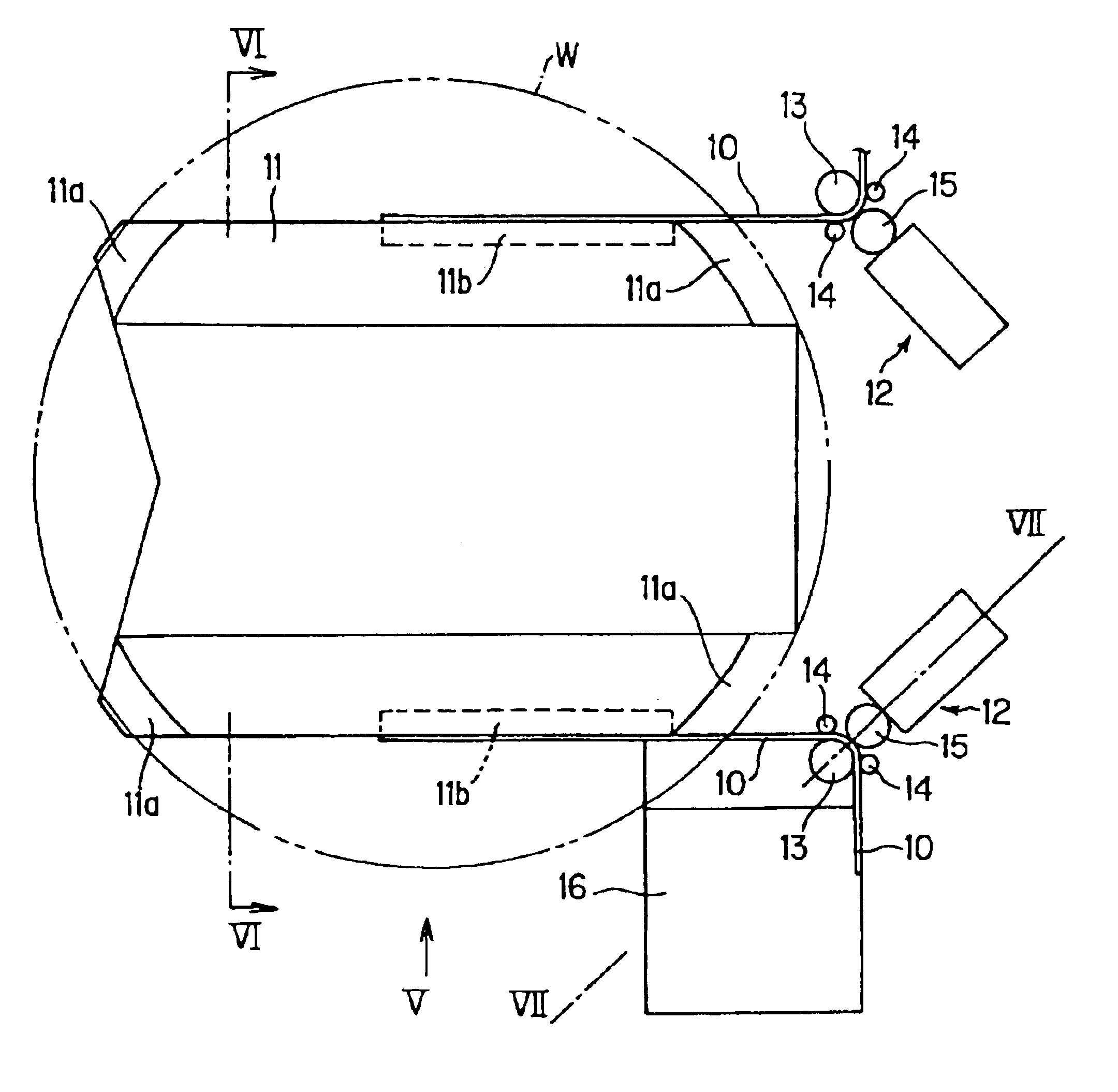
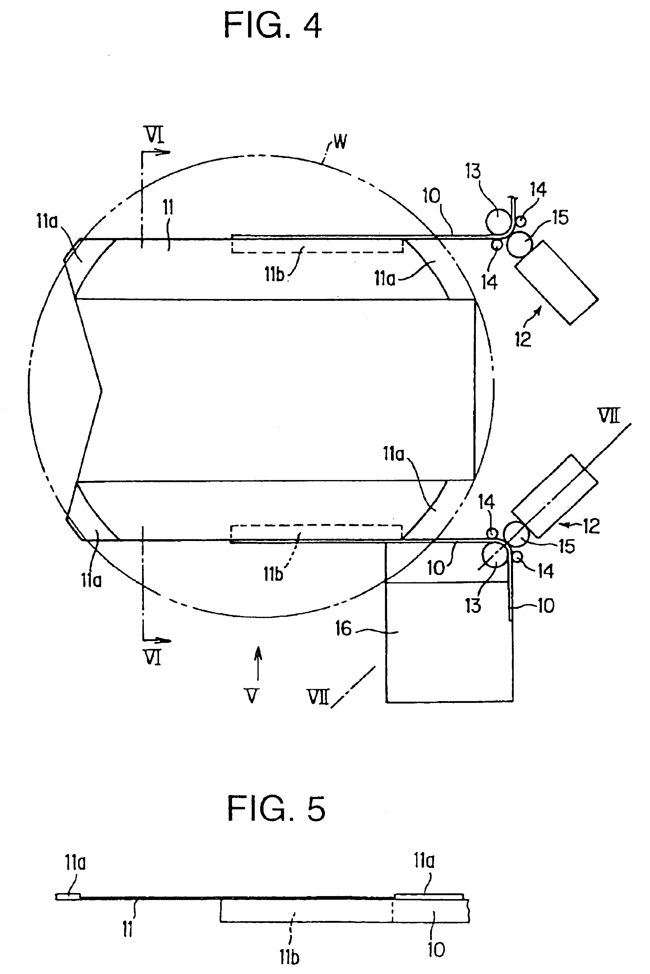
The transfer apparatus 4 is an apparatus for transferring the the work-piece W to the process chamber 1 from the outside via the transfer chamber 2 and transferring the work-piece W back to the transfer chamber 2 after processing of the work-piece is completed. The transfer apparatus 4 is constructed such that: when the gate valve 3 is opened, its tape is pulled out successively and made to be in an extended state to thereby perform transfer to and t...

second embodiment

FIG. 8 is a cross-sectional side view showing a second embodiment of the present invention. As for the First embodiment, the holder hand transfer bodies are constructed in two stages of an upper stage and a lower stage in the second embodiment.

The second embodiment differs from the first embodiment in the following points: the holder hand transfer body 6 (or 7) has a linear guide portion 26 of two stages, and this linear guide portion 26 attaches the work-piece holder hand 11 to its tip end and supports the object, to thereby make the work-piece holder hand 11 move feed and astern while the tape 10 extends and shrinks the linear guide portion 26 of two stages; a width direction of the tape 10 is made to match a horizontal direction, and a direction changing means 25 rotates the rear end side of the tape 10 by 90° downward to thereby perpendicularly lead the tape 10 to an empty space under a support base of the vacuum apparatus; and a magnet which moves linearly is used as a driving ...


PUM


Abstract

A vacuum apparatus has a process chamber for processing a workpiece and a transfer apparatus for positioning the workpiece in the process chamber and for removing the workpiece from the process chamber. The transfer apparatus has a pair of generally parallel and spaced-apart transfer bodies and a workpiece holder connected to the transfer bodies for supporting the workpiece. A feeding mechanism feeds the transfer bodies in a longitudinal direction thereof to position the workpiece holder and the workpiece in the process chamber.

Description

BACKGROUND OF THE INVENTION1. Field of the InventionThe present invention relates to a vacuum apparatus and a transfer apparatus for use with a semiconductor manufacturing apparatus, a manufacturing apparatus for a flat panel display, or the like.2. Prior ArtIn a manufacturing process of a semiconductor or a flat panel display, a work-piece such as a silicon wafer is subject to various kinds of processes such as etching, CVD, ashing, RTP, and dry cleaning. These processes need to be conducted in a clean and high vacuum, and, in order to obtain this vacuum environment, a large-scale apparatus is used when the work-piece is transferred to and transferred from the vacuum apparatus.As a conventional apparatus of this kind, there is one provided with a load chamber for transfer to the vacuum chamber the work-piece from the outside under the atmospheric pressure and an unload chamber for transfer from the vacuum chamber the work-piece having finished processes to the outside. FIG. 9 shows...

Claims


Application Information

Patent Timeline
Patent Type & Authority Patents(United States)
IPC IPC(8): H01L21/687H01L21/677H01L21/67B65G49/06B65G49/07H01L21/02
CPCH01L21/67742H01L21/68707Y10S414/135H01L21/02
Inventor YAMASHITA, YOSHIHIROENOMOTO, YOSHIHIRO
Owner SEIKO INSTR INC
Why Eureka
Try Eureka