
Passive optical network system

a passive optical network and optical communication technology, applied in the field of configuration of optical communication systems, can solve the problems of increasing the number of subscriber units, increasing the distance of optical fibers, and increasing the complexity of the system, so as to increase the number of accommodated subscriber units, the effect of extending the communication distance and reducing the development cos

Inactive Publication Date: 2013-03-05
HITACHI LTD
View PDF6 Cites 5 Cited by
  • Summary
  • Abstract
  • Description
  • Claims
  • Application Information

AI Technical Summary

Benefits of technology

This approach allows for the efficient expansion of PONs by maintaining consistent optical receiver performance across varying distances and bit rates, reducing development and maintenance costs while preventing receiver damage, thus enhancing the overall cost-effectiveness of the optical access network.

Problems solved by technology

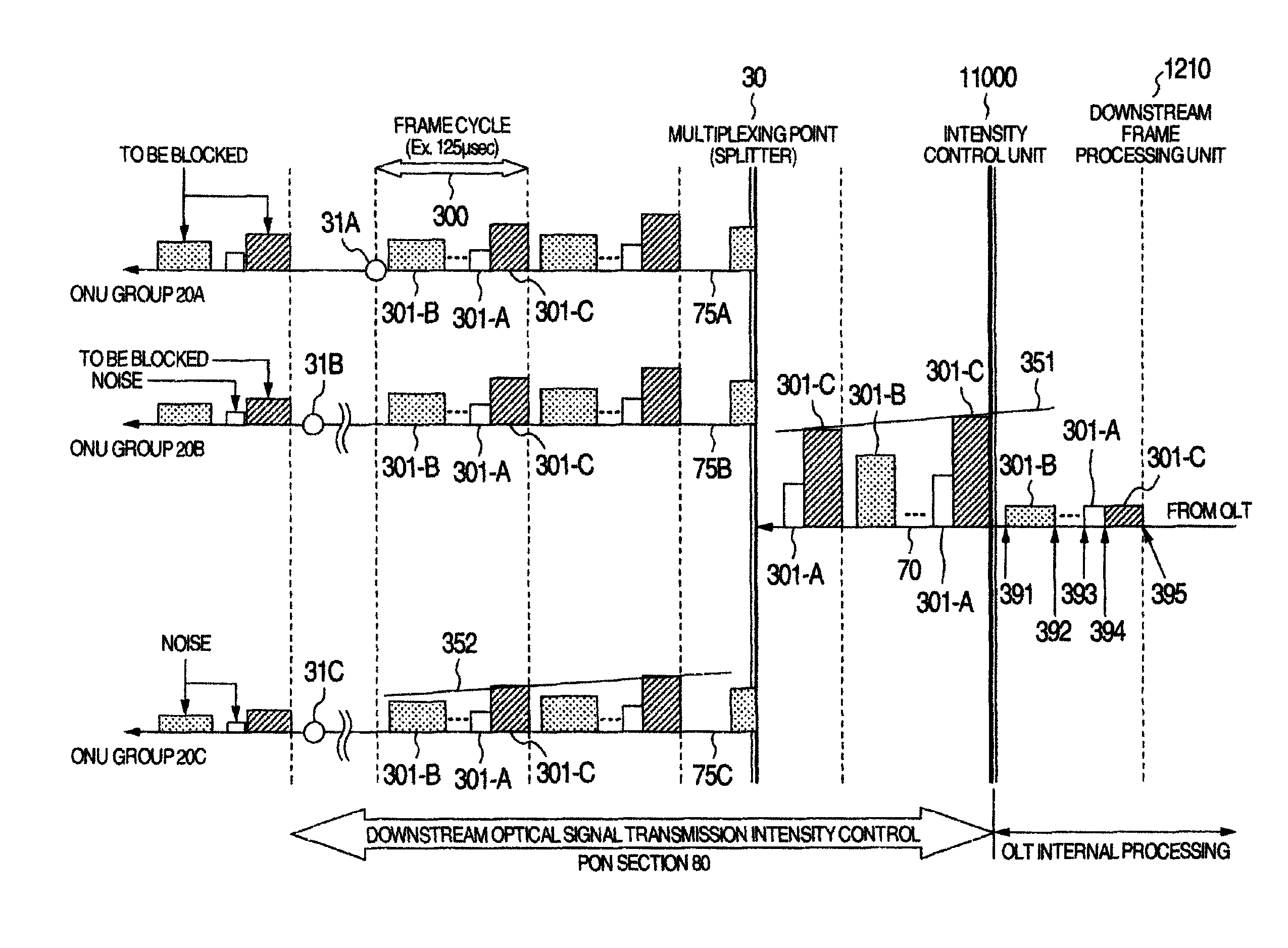
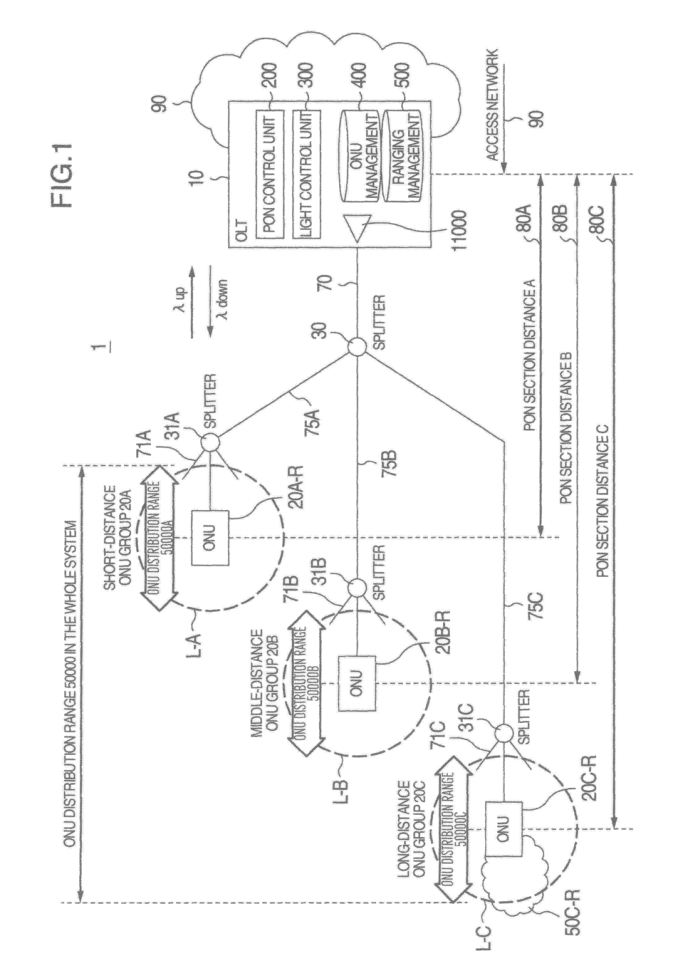
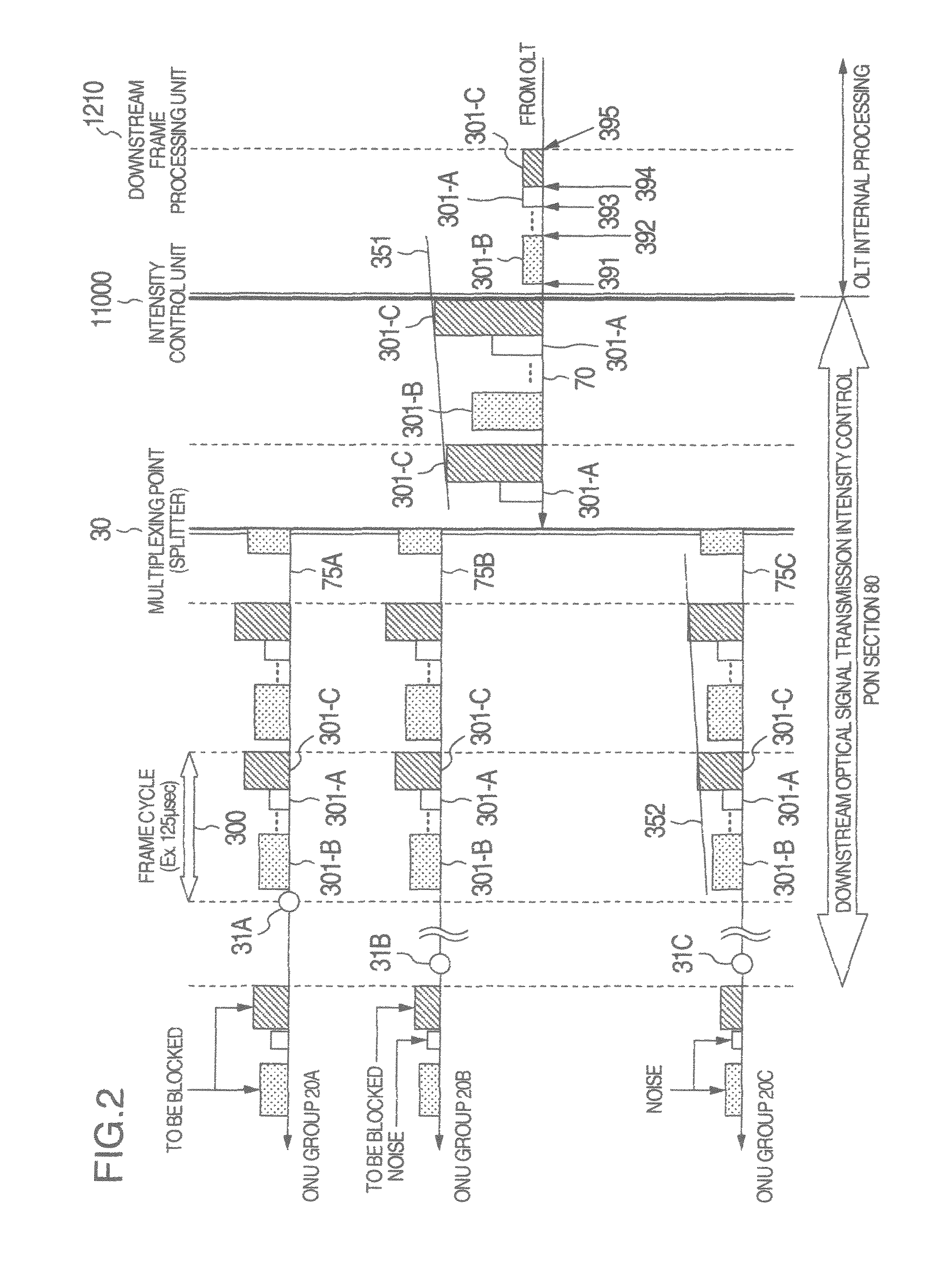
On the other hand, due to the expansion of the ONU distribution, however, there arises a problem that the intensity of a downstream signal to be sent out from the OLT to the ONUs varies largely between the closest ONU to the OLT and the farthest ONT from the OLT so that the intensity may exceed the allowable range of optical receiving sensitivity in each optical receiving device.
The problem results from the fact that the variation in the distance of an optical fiber through which an optical signal passes till arrival at each ONU becomes larger than the background art.
It is, however, difficult to improve the performance of each optical receiving device on a large scale in a short time.
It is therefore likely that a signal which can be received by an ONU close to the OLT cannot be recognized by an ONU distant from the OLT but, on the contrary, a receiving device in the close ONU may be damaged when the close ONU receives an optical signal transmitted to the distant ONU.

Method used


Image

  • Passive optical network system
  • Passive optical network system
  • Passive optical network system

Examples


second embodiment

[0122]FIGS. 20A and 20B show a second embodiment in which header information is collected in the head position of a superframe. Description will be made below on the assumption that an ONU 20A is one of the ONUs belonging to the ONU group 20A, an ONU 20B is one of the ONUs belonging to the ONU group 20B, and an ONU 20C is one of the ONUs belonging to the ONU group 20C.

[0123]The superframe 5105 according to this embodiment is arranged into a frame which includes a header 5110 and a payload 5120 for one ONU in each of the three ONU groups 20A, 20B and 20C and whose frame length is 375 microseconds, which is three times as long as 125 microseconds. The header unit 5110 and the payload unit 5120 include a header and a payload to be transmitted with certain light intensities respectively. When a plurality of light intensity signals are multiplexed and transmitted in the form of the superframe 5105, both header units and payload units are transmitted in order of increasing light intensity...

first embodiment

[0127]As described above, in this embodiment, blocking sections 5110B and 5110C are defined as an additional header region 5520 for the ONU 20A to allow the ONU 20A to properly receive the data unit 5120A after waiting in the blocking sections 5110B and 5110C. The following measure is used for allowing the ONU 20A to start receiving the payload (GEM frame) addressed to the ONU 20A as soon as the additional header region 5520 is terminated. First, assume that the length of each header unit 5110A, 5110B, 5110C is fixed. As a result, the interval between received times of headers is fixed in each ONU group. That is the frame length of the superframe 5105 is always fixed. When an individual ONU 20 is started up as described in the first embodiment, the ONU 20 is notified of time information, arrival timing (that is, normal operation start time) of a superframe (header unit 5110A, 5110B or 5110C) to be received first, and superframe length.

[0128]Thus, for example, each ONU of the ONU gro...


PUM


Abstract

When a neighbor ONU receives a signal with light intensity high enough to secure communication between an OLT and a remote ONU, the light intensity may be excessively high to damage a receiver of the neighbor ONU. In order to avoid such a problem, each ONU is notified of a downstream signal transmission plan (downstream light intensity map) prior to transmission of a downstream signal. Each ONU receives the downstream light intensity map (light intensity transmission schedule of downstream signal) in advance. Thus, the neighbor ONU can block or attenuate an optical signal addressed to the remote ONU, and the remote ONU can determine normal operation even when the remote ONU cannot receive a signal addressed to the neighbor ONU. Thus, the remote ONU can be prevented from issuing a wrong error signal.

Description

INCORPORATION BY REFERENCE[0001]The present application claims priority from Japanese application JP2010-084791 filed on Apr. 1, 2010, the content of which is hereby incorporated by reference into this application.BACKGROUND OF THE INVENTION[0002]The present invention relates to a configuration of an optical communication system in which optical transmission lines are shared among a plurality of subscriber units, a method for operating the optical communication system, and system expansion such as extension of a transmission distance or increase in the number of accommodated subscribers in the system.[0003]With an increasing demand for communication using broadband, access lines for users have been being shifted to large-capacity access lines using optical fibers in place of access technology based on telephone lines such as DSL (Digital Subscriber Lines). For recent access line services, PON (Passive Optical Network) systems (hereinafter also referred to as PONs simply or as optica...

Claims


Application Information

Patent Timeline
Patent Type & Authority Patents(United States)
IPC IPC(8): H04J14/00
CPCH04B10/0793
Inventor NIIBE, MASAOMIZUTANI, MASAHIKOFUJIOKA, SHINYA
Owner HITACHI LTD
Learn More