
Thermal imaging process and products made therefrom

Inactive Publication Date: 2005-09-08
EI DU PONT DE NEMOURS & CO
View PDF21 Cites 2 Cited by
  • Summary
  • Abstract
  • Description
  • Claims
  • Application Information

AI Technical Summary

Benefits of technology

[0020] One advantage of the invention is that material that is thermally transferred can be selected from a wide variety of materials. Imaging materials are typically applied to the receiver in thin layers of less than 50microns in thickness, which places a limit on the size of the imaging material that is thermally transferred in at least one dimension of imaging material.
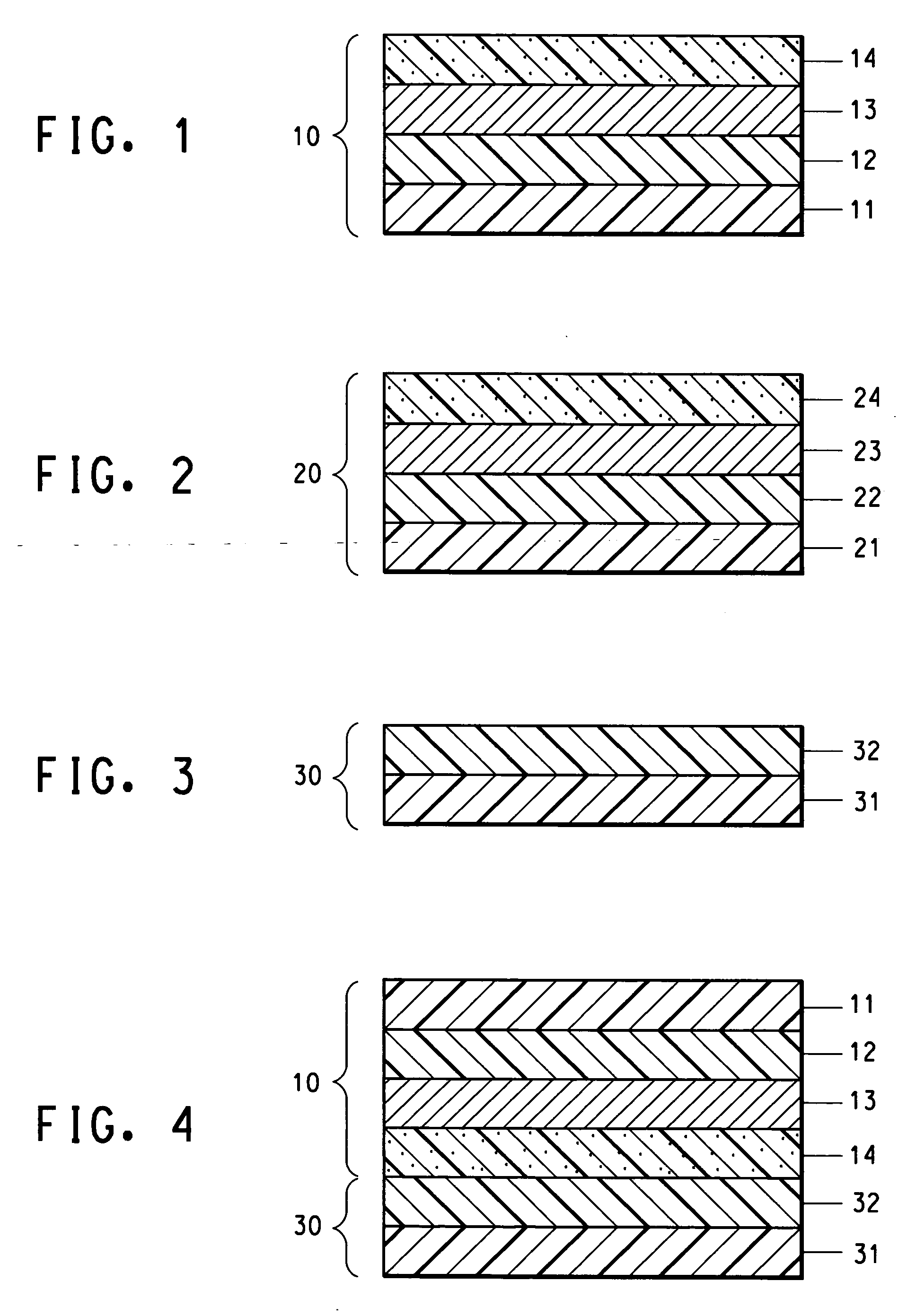
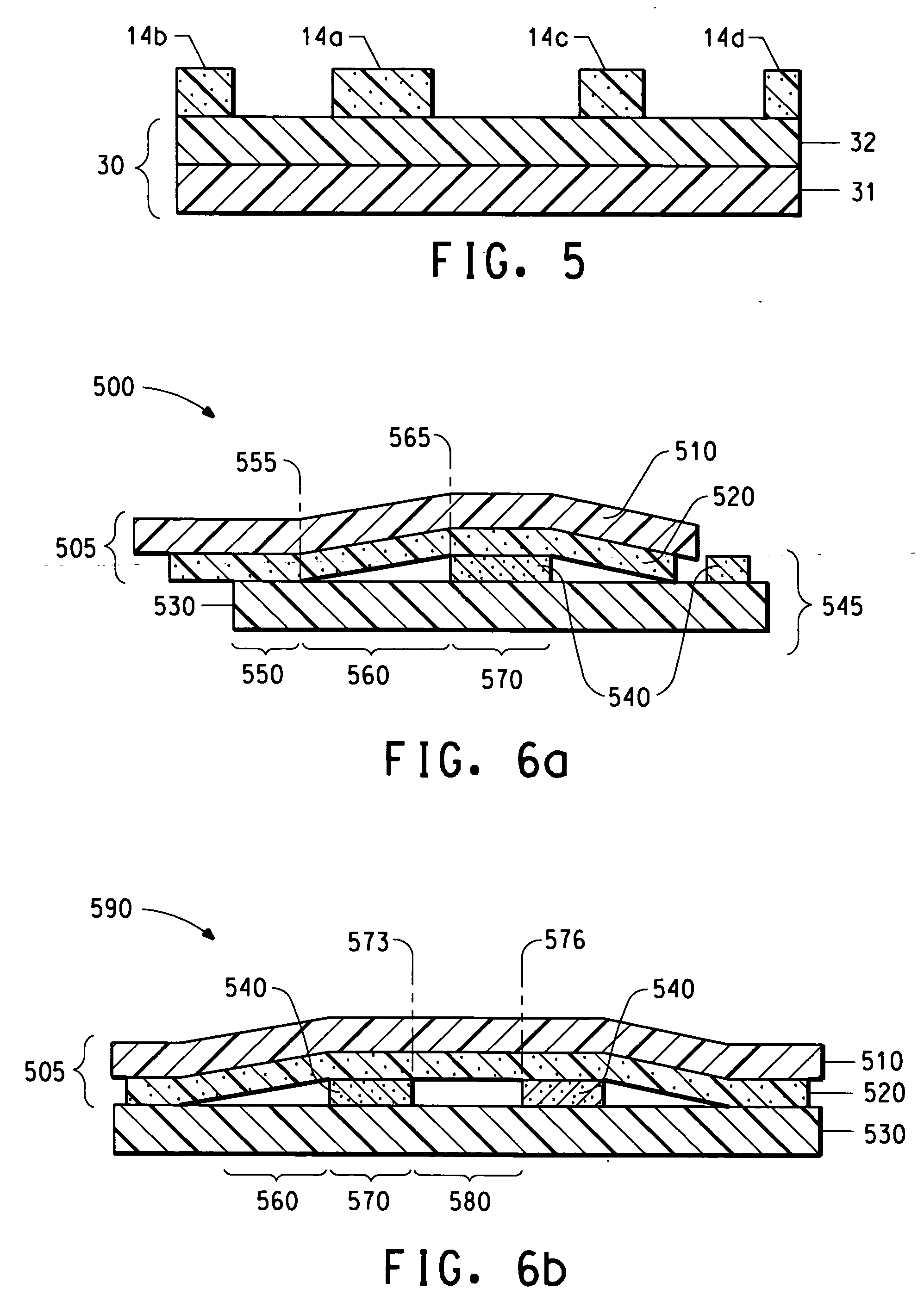
[0021] Texturing Donor `FIG. 1 shows a texturing donor (10) useful for thermal transfer imaging in accordance with the process of this invention. There comprises a texturing layer (14) and a support having a coatable surface that comprises an optional ejection layer (12) and optionally a heating layer (13). Each of these layers has separate and distinct functions. A support layer for the texturing donor (11) is also present. In one embodiment, the optional heating layer (13) may be present directly on the support layer (11). Texturing Layer:
[0022] Applying a layer of a composition comprising a texturing material to a support forms the texturing layer (14). Preferred properties of the texturing layer can be understood by considering the use of the texturing layer in texturing a receiver. When portions of the applied layer are transferred to a receiver, the transferred portions provide for a separation of the imaging material and the receiver, proximate to the transferred portions, in a subsequent assemblage. In order to provide this separation, it is preferred that the transferred portions not change in thickness by flow in the subsequent assemblage. In order to carry out imaging of a subsequent assemblage in a predictable fashion, it is preferred that the transferred portions provide a predictable distance of separation.
[0023] In one embodiment, some part of the volume of the texturing layer is transferred unchanged to the receiver to form the texture, for example by ablative mass transfer or laser induced film transfer. In one embodiment, the texturing layer includes (i) a texturing material which is a binder, and optionally (ii) another texturing material such as a solid. Examples of solids include particles, typically fine particles such as pigments or fillers. The texturing layer can also include a dye, plasticizer, or other components of known utility for transferable layers of donors. Suitable texturing layers can be provided by well-known donors, such a donors used in color proofing that provide a volume of transferred material being transferred to a receiver. Texturing layers can be colored by colorants such as pigments or dyes.
[0024] The binder of the texturing layer can be a polymeric material having a decomposition temperature that is greater than about 250° C. and specifically greater than about 350° C. The binder is preferably film forming and coatable from solution or from a dispersion. Binders having melting points less than about 250° C. or plasticized to such an extent that the glass transition temperature is less than about 70° C. are typical. However, easily liquifiable and heat-fusible binders, such as low-melting waxes should be avoided as the sole binder if such binders flow and are not durable, although they are useful as cobinders in decreasing the melting point of the texturing layer.
[0025] If the binder is to be transferred along with another texturing material, it is typical that the polymer of the binder not self-oxidize, decompose or degrade at the temperature achieved during the laser exposure. By virtue of this selection, the exposed areas of the texturing layer comprising the texturing material and binder can be transferred intact for improved durability.

Problems solved by technology

Transfer failure, in which imaging material fails to transfer, has been a problem in thermal transfer processes.

Method used


Image

  • Thermal imaging process and products made therefrom
  • Thermal imaging process and products made therefrom
  • Thermal imaging process and products made therefrom

Examples


##ic example 2

PROPHETIC EXAMPLE 2

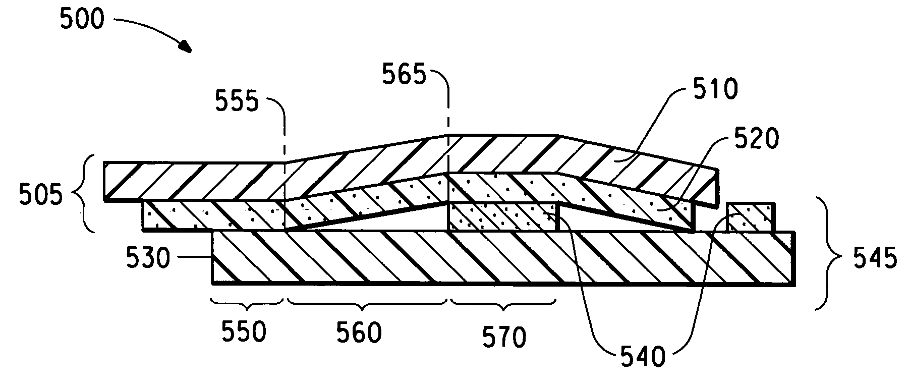
[0136] A color filter in accordance with this invention can be made using a texturing transfer of a texturing material according to a texturing pattern. One embodiment of a texturing pattern is designed to place texturing material into the vicinity of the thin film transistor area of a receiver element comprising Corning 1737glass with a chrome black mask as in Comparative Example 1A.

[0137] A first thin-film-transistor-area-partial-covering texturing pattern can comprise a pattern of 2,359,296identical square areas 27microns on each side, arranged in 3072columns of 768rows. The pitch of the rows would be 279 microns; the pitch of the columns would be 93 microns. The pattern would be exposed within the active area so that the leftmost column of the pattern abuts the leftmost edge of the active area, and the topmost edge of the top row of the pattern is 252 microns below the top edge of the active area. This pattern is intended to cover a square portion of the thin...

##ic example 3

PROPHETIC EXAMPLE 3

[0141] A color filter in accordance with this invention can be made using a texturing transfer of a texturing material according to a texturing pattern. One embodiment of a texturing pattern is designed to place texturing material into the vicinity of the thin film transistor area of a receiver element comprising Corning 1737glass with a organic black mask as in Comparative Example 1B, using only one third of the number of areas of the texturing pattern used in example 2.

[0142] A sparse first thin-film-transistor-area-partial-covering texturing pattern can comprise a pattern of 786,432 identical square areas 27microns on each side, arranged in 1024 columns of 768rows. The pitch of the rows and the columns would be 279 microns.

[0143] Other than the sparse pattern to be used in Example 3 and the receiver element having an organic black mask instead of a chrome black mask, the example is identical to Example 2.

##ic example 4

PROPHETIC EXAMPLE 4

[0144] A color filter in accordance with this invention can be made using a texturing transfer of a texturing material according to a texturing pattern. One embodiment of a texturing pattern is designed to place texturing material into the designated window area of a receiver element comprising Corning 1737. The receiver element could optionally comprise a black mask, or a black mask could be added in a subsequent step, including an organic black mask being added in a thermal imaging step. This example starts with bare glass as in Comparative Example 1C, and adds an organic black mask after texturing and before the use of the three colored donor elements. The texturing donor material is transparent so that it has no positive or negative effect on the filtering properties of the final color filter, regardless of its presence or absence.

[0145] A window-occupying texturing pattern can comprise a pattern of 786,432identical rectangular areas 29 microns wide and 93 mi...


PUM

PropertyMeasurementUnit
Areaaaaaaaaaaa
Transparencyaaaaaaaaaa

Abstract

The invention relates to a method for the manufacture of a color filter element on a receiver element having a window area and / or a latent or present mask area comprising thermally transferring a texturing material from a thermal transfer texturing donor to the receiver element prior to thermally transferring a pigment colorant, wherein the texturing material is transferred to (a) at least one of the mask areas or (b) one of the mask areas and a portion of the window area. Alternatively, the texturing material is transferred to at least a portion of the mask area and no more than a portion of the window area.

Description

BACKGROUND OF THE INVENTION [0001] The invention relates to a method for the manufacture of a thermal transfer element. More specifically, the invention relates to the use of a texturing donor to improve the thermal transfer process. [0002] In known thermal transfer processes an imaging material, typically a pigment, is thermally transferred, using a laser, from a donor element to a receptor element. Such laser induced thermal transfer processes have been described for use in manufacturing various elements including monochrome or color prints, proofs, filters for liquid crystal display devices, security printing applications, machine readable items, and printed circuits. [0003] Transfer failure, in which imaging material fails to transfer, has been a problem in thermal transfer processes. Thus there is a need for thermal transfer processes which minimize or overcome the problem of transfer failure. SUMMARY OF THE INVENTION [0004] The invention relates to a method for the manufacture...

Claims


Application Information

Patent Timeline
IPC IPC(8): B05D5/06B41M3/00B41M5/00B41M5/24B41M5/26B41M5/382B41M5/52G02B5/20
CPCB41M3/003G02B5/201B41M5/38207B41M5/265B41M3/00B41M5/00
Inventor CASPAR, JONATHAN V.
Owner EI DU PONT DE NEMOURS & CO
Learn More