
Method and apparatus for crystal drift compensation

a technology of crystal drift and compensation circuit, applied in the field of communication circuits, can solve the problems of large capacitors, inability to use a cost-effective stand-alone crystal oscillator in a cellular system, and the output of a crystal oscillator tends to drift slightly, so as to achieve the effect of reducing nois

Inactive Publication Date: 2005-09-08
TEXAS INSTR INC
View PDF2 Cites 21 Cited by
  • Summary
  • Abstract
  • Description
  • Claims
  • Application Information

AI Technical Summary

Benefits of technology

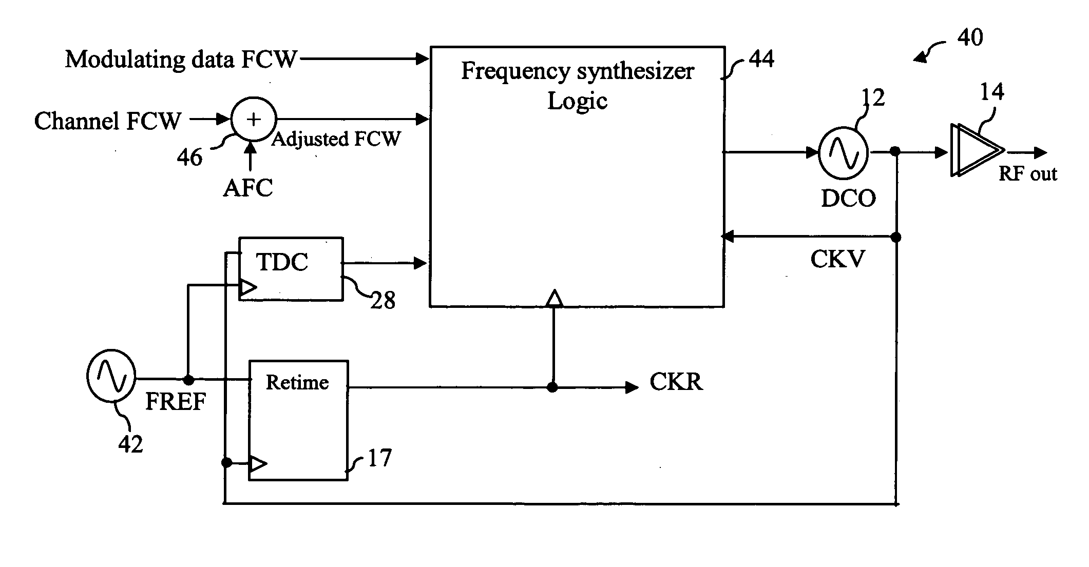
[0012] The present invention provides significant advantages over the prior art. First, a simple crystal oscillator can be used without complex stabilizing circuitry, which significantly reduces the cost of the circuit. Second, the design eliminates the noise associated with switching large capacitors to stabilize the reference frequency.
[0014] The aspect of the invention reduces noise attributable to circuitry used to stabilize the output of a crystal oscillator, where the logic in the control circuitry does not switch synchronously with the output signal.

Problems solved by technology

Unfortunately, the output of a crystal oscillator tends to drift slightly with age and temperature.
Due to the stringent requirements, it is not possible to use a cost-effective stand-alone crystal oscillator in a cellular system without some frequency tuning support from the basestation.
Unfortunately, a DCXO circuit requires large capacitors to perform frequency corrections on the crystal oscillator.
Using this technique, therefore, is extremely expensive, particularly for highly-integrated transceivers in a deep-submicron CMOS process.
Further, the switching of a large number of capacitors in the DCXO circuit to adjust the reference frequency can result in frequency beating events that exhibit themselves as spurs in the generated output.

Method used


Image

  • Method and apparatus for crystal drift compensation
  • Method and apparatus for crystal drift compensation
  • Method and apparatus for crystal drift compensation

Examples


Embodiment Construction

[0027] The present invention is best understood in relation to FIGS. 1-4 of the drawings, like numerals being used for like elements of the various drawings.

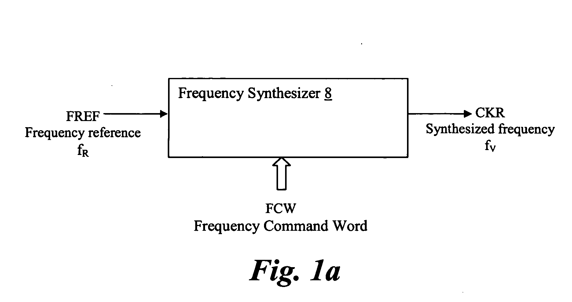
[0028]FIG. 1a illustrates the general operation of a frequency synthesizer 8. RF frequency synthesizer 8 is used as a local oscillator (LO) that performs frequency translation in wireless transmitters and receivers. The frequency reference (FREF) clock at frequency fR contains the only reference timing information for the frequency synthesizer to which the phase and frequency of the RF output are to be synchronized. The RF output CKV at variable frequency (fV) is related to the reference frequency (fR) according to the following formula: fV=N×fR, where, N=FCW is a fractional frequency division ratio.

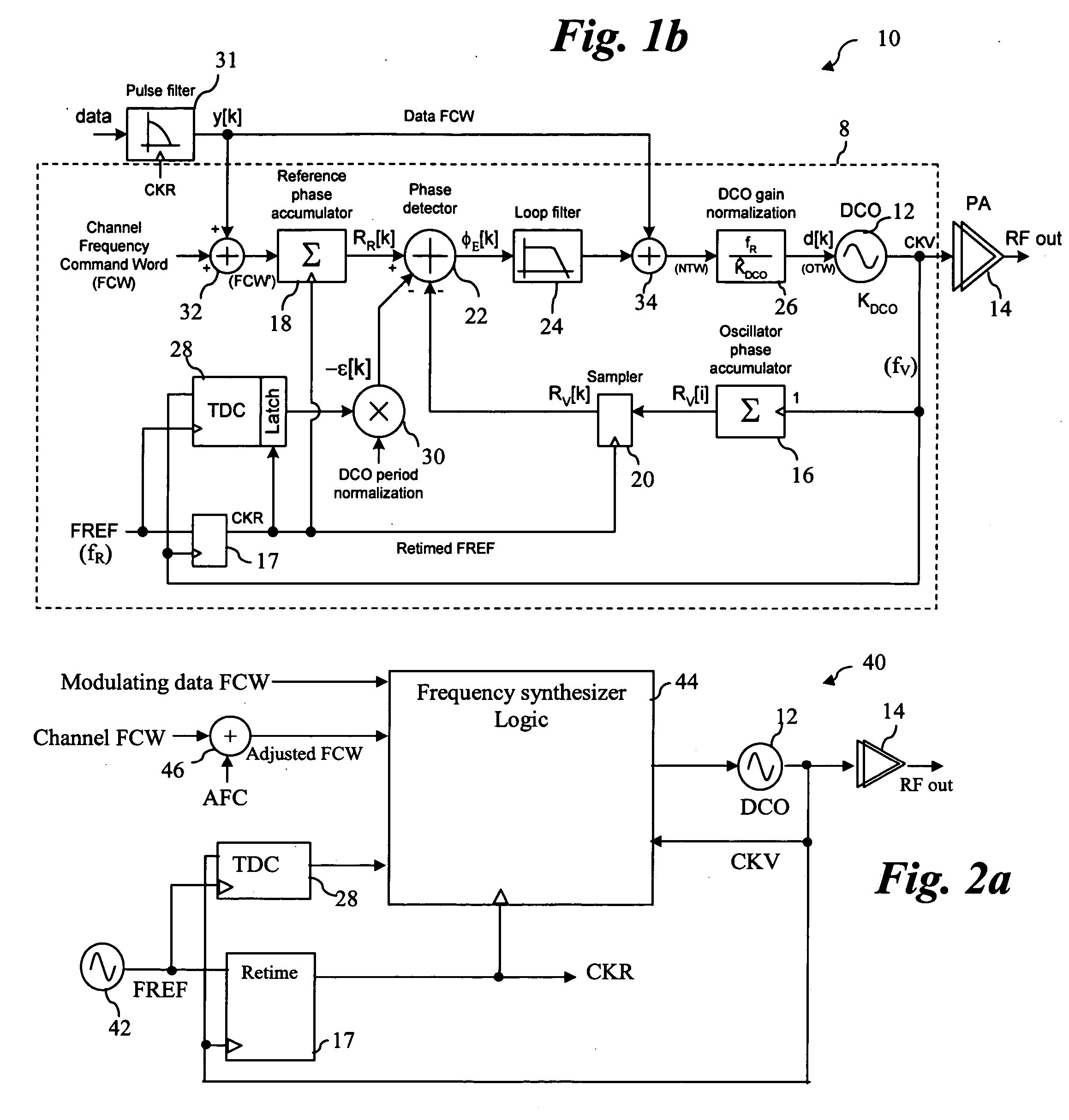
[0029]FIG. 1b illustrates a block diagram of an RF transmitter 10 based on an all-digital phase-locked loop (ADPLL) frequency synthesizer with a digital direct frequency modulation capability. This circuit is described in detail in...


PUM


Abstract

A mobile device includes frequency synthesizer circuitry for generating a channel frequency at a multiple of a reference frequency. The reference frequency is generated by a free-running crystal oscillator, without frequency stabilization circuitry. Variations in the output of the crystal oscillator are compensated by adjusting the multiplication factor of the frequency synthesizer.

Description

CROSS-REFERENCE TO RELATED APPLICATIONS [0001] This application claims the benefit of the filing date of copending provisional application U.S. Ser. No. 60 / 550,919 filed Mar. 5, 2004, entitled “Crystal Drift Compensation in a Mobile Phone” to Staszewski et al.STATEMENT OF FEDERALLY SPONSORED RESEARCH OR DEVELOPMENT [0002] Not Applicable BACKGROUND OF THE INVENTION [0003] 1. Technical Field [0004] This invention relates in general to communication circuits and, more particularly, to a method and apparatus for correcting crystal drift in a communication circuit. [0005] 2. Description of the Related Art [0006] Many communication devices use a crystal oscillator circuit as a frequency reference. The frequency output of the crystal oscillator circuit is multiplied by a known factor in a frequency synthesizer circuit to obtain a desired channel frequency. Typically, the reference frequency generated by the oscillator is in the range of tens of MHz, while the channel frequency is in the ra...

Claims


Application Information

Patent Timeline
IPC IPC(8): H04L27/04
CPCH03C3/0941H03C3/095H03L2207/50H03J7/047H03L1/00H03C3/0966
Inventor STASZEWSKI, ROBERT B.LEIPOLD, DIRK
Owner TEXAS INSTR INC
Learn More