
Bone harvesting device and method

a bone harvesting and bone technology, applied in the field of bone harvesting devices and methods, can solve the problems of time-consuming and waste of bone stock, difficult control of the depth to which the patella bone is cut, and difficult control of the depth of the bone block, etc., to achieve the effect of convenient harvesting and more reliabl

Inactive Publication Date: 2005-09-01
ARTHROCARE
View PDF10 Cites 20 Cited by
  • Summary
  • Abstract
  • Description
  • Claims
  • Application Information

AI Technical Summary

Benefits of technology

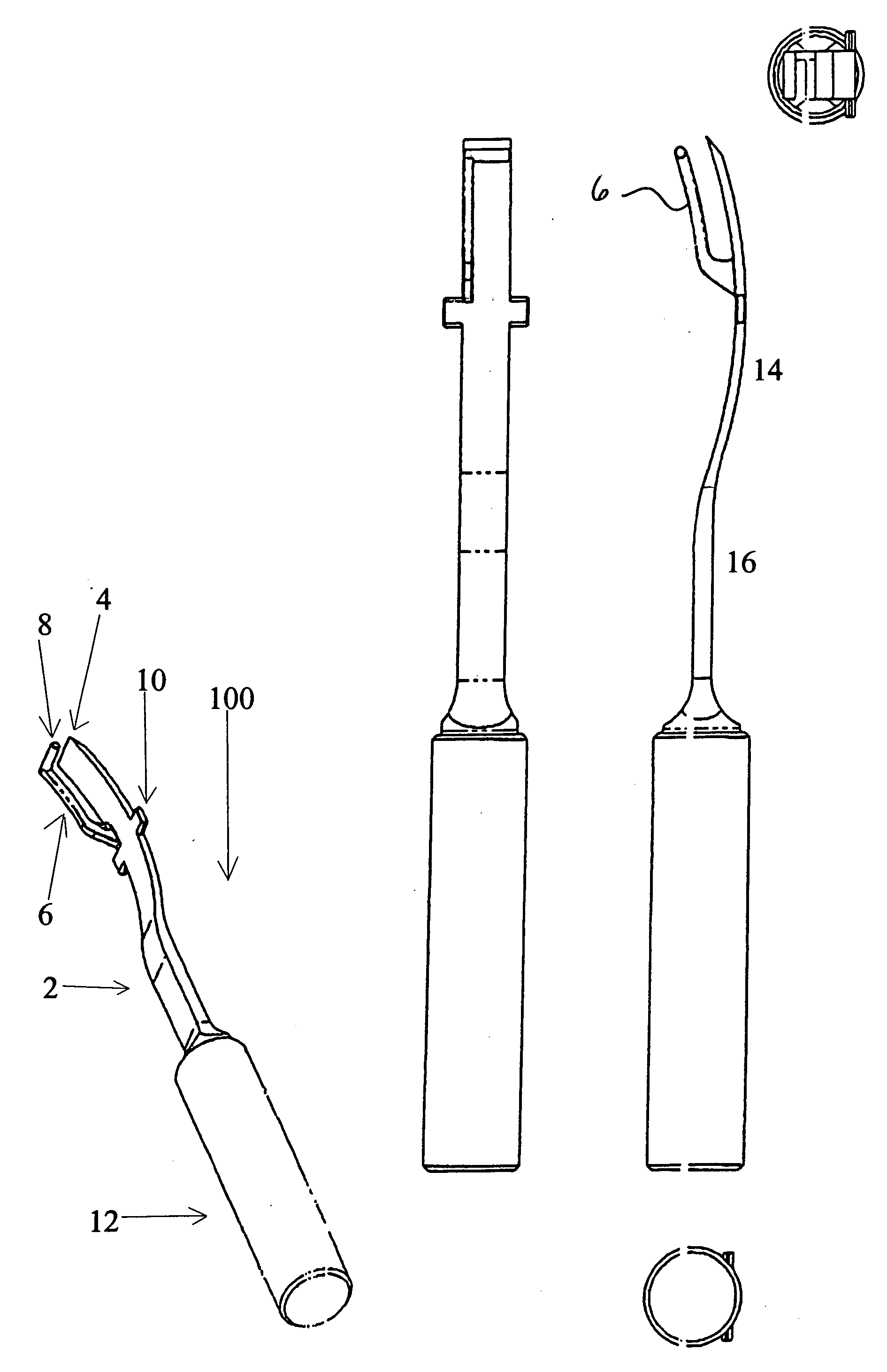
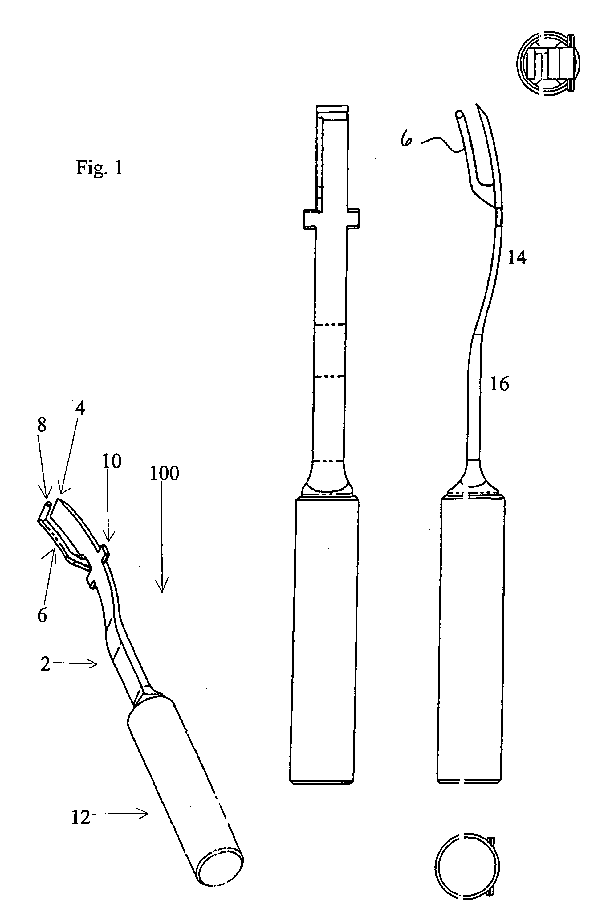
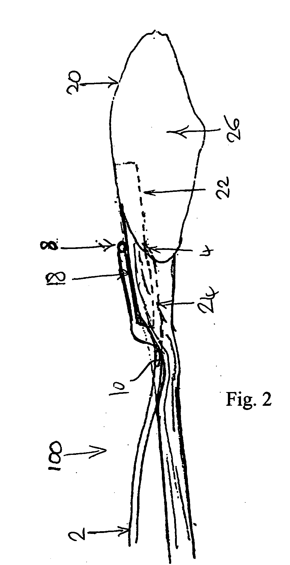
[0008] Thus, in contrast to conventional bone cutting devices which generally aim to provide a surgeon with greater control over the device, the invention aims to restrict movement, in at least one dimension, by bearing on a tissue surface. As used in this context, the term “tissue” may include bone or soft tissue, typically bone or tendon. The dimension, most advantageously depth, may be tightly controlled, the guide preferably rigidly determining a maximum value. However, the guide may have some degree of resilience or flexibility to allow the surgeon to make fine adjustments to the controlled dimension based on tactile feedback from the guide.
[0009] Preferably, the bone block harvester is arranged to determine a dimension of the bone block in a direction substantially perpendicular to the direction of motion of the cutter. This may allow the surgeon one or two other degrees of freedom to control depth or width with a particular harvester being optimised for a particular depth.
[0011] In a convenient arrangement, the guiding element is coupled by an elongate arm to the cutter. Advantageously, the cutter is elongate and the elongate arm extends substantially parallel to and spaced from the elongate cutter. This arrangement is both readily manufactured and easily usable. Preferably the spacing of the arm and cutter determines one dimension of the bone block.
[0015] The guiding element preferably extends in the direction of the width of the blade further than the width of the elongate arm; this enables a more reliable guide without requiring an unwieldy attachment arm, and may enable the guiding element to be hooked onto a tendon. Preferably the guiding element has substantially the same width as the cutter blade.
[0016] The cutting guide is preferably substantially blunt and / or may have rounded contact edges. In contrast, the cutter preferably has a sharpened flat distal edge (although it may in some cases have a sharpened point or curved edge). This facilitates harvesting a generally rectangular section (e.g. cuboid or trapezoid) portion of bone. The cutter may be elongate and the side edges of the cutter are preferably less sharp than the distal edge, optionally substantially blunt.
[0018] Preferably the body is elongate and comprises a substantially linear proximal portion and a curved distal portion; this facilitates manipulation. The curved distal portion of the harvester may allow the handle of the harvester to be held at an angle to the direction of cutting, which is highly advantageous where the region proximal the cutting edge is obstructed.

Problems solved by technology

A problem faced in bone block harvesting, particularly in graft surgery, is harvesting the bone blocks accurately and quickly, while minimising damage to the donor site.
This technique may be problematic, for example in harvesting bone blocks associated with the patellar tendon, in which procedure the nature of the patella makes controlling the depth to which the patella bone is cut very difficult.
The depth of the bone block is especially hard to control.
As a result irregular bone blocks are produced that have to be subsequently cut to size and shaped, which is time consuming and wastes bone stock.
In addition, in prior art methods using a powered bone saw there is a risk of thermal damage to the surrounding tissue at the donor site caused by the action of the saw.
In this technique the dimensions of the bone block are controlled, but it has the disadvantage of added complexity.
Extra surgical steps are required to attach and subsequently remove the template, and the process of cutting to the template is also time consuming, so the duration of the surgery is increased and the demands on the surgeon are greater.

Method used


Image

  • Bone harvesting device and method
  • Bone harvesting device and method
  • Bone harvesting device and method

Examples


Embodiment Construction

[0031] In a preferred embodiment, described below by way of example only, there is provided a bone block harvester for use in Anterior Cruciate Ligament graft surgery using a Patellar Tendon graft.

[0032] Anterior Cruciate Ligament (ACL) reconstruction surgery involves replacing a torn ACL with a graft ligament that can be taken from the patient's own body (autologous) or made from synthetic material or from a cadaver (allograft). Of the total number of surgeries performed around 85% are performed using autologous grafts. Of this number approximately 65% are performed using a graft ligament taken from the central third of the Patellar Tendon, including bone from the superior tibia and the patella. These are referred to as Bone-Patellar Tendon-Bone (BPTB) grafts. There are several alternative grafts available for ACL reconstruction, including hamstring grafts and allografts, but the BPTB graft offers the advantage that the bone blocks heal into the surrounding bone of the patient aft...


PUM


Abstract

A surgical device and method are disclosed for harvesting bone portions. The device has a guide which facilitates control of at least one dimension of the harvested portion. Embodiments of the invention are particularly, but not exclusively, suited to harvesting bone portions for graft surgery, particularly patella tendon grafts.

Description

BACKGROUND OF THE INVENTION [0001] The present invention relates to bone harvesting device and method. FIELD OF THE INVENTION [0002] The Invention relates particularly but not exclusively to devices and methods for harvesting bone samples. Embodiments are particularly but not exclusively optimised for use in ligament graft surgery. DESCRIPTION OF THE RELATED ART [0003] A problem faced in bone block harvesting, particularly in graft surgery, is harvesting the bone blocks accurately and quickly, while minimising damage to the donor site. It is desirable to reduce the operative time as much as possible, since a shorter operation generally results in faster recovery for the patient and a reduced risk of complications. In addition, the bone blocks harvested should have a precise desired size and shape to allow them to be positioned in their intended destination, which may be a bone tunnel for example, and to provide a good fit with the destination site to facilitate fusion of the bone bl...

Claims


Application Information

Patent Timeline
Patent Type & Authority Applications(United States)
IPC IPC(8): A61B17/16A61B17/17A61B17/58A61B19/00
CPCA61B17/1604A61B17/1635A61B2019/304A61B17/1714A61B17/1767A61B17/1677A61B2090/034
Inventor REAY-YOUNG, CLIVE
Owner ARTHROCARE
Learn More