Lamellar seal for a turbomachine

a turbomachine and seal technology, applied in the field of turbomachines, can solve the problems of limiting reducing the service life of the seal, so as to achieve cost-optimized production

Inactive Publication Date: 2010-09-30
ANSALDO ENERGIA SWITZERLAND AG
View PDF20 Cites 14 Cited by
  • Summary
  • Abstract
  • Description
  • Claims
  • Application Information

AI Technical Summary

Benefits of technology

[0017]One of numerous aspects of the present invention involves largely avoiding the aforesaid disadvantages of a lamellar seal and a geometry of the seal lamellae which allows individual modules or complete seals to be reliably fixed by simple fitting together of the components concerned, so that the components can then be interconnected in a distortion-free manner by a joining process, for example by a soldering process according to WO 2005 / 095829.
[0018]Another aspect of the present invention relates to a seal or seal module from an exactly matching pair of lamella and carrier plate. Both the installation angle w1 and the gaps between the lamellae are specified with high accuracy, in this case by precisely cut, slightly wedge-shaped pockets in the carrier plate. The pockets in this case are constantly oriented so that each individual lamella is exactly at the angle w1, which is specified by the design, to the rotor surface. Each individual lamella has an associated pocket in the carrier plate. In this case, when fitting the lamellae into the carrier plate, a definite matching and consequently assurance of the positional accuracy ensues as a result of form-fitting insertion of the lamellae into the pockets in the carrier plate. For best possible fixing and guiding of the seal lamellae in the carrier plate, the lamellae are provided with suitable side arms which engage in the precise pockets of the carrier plate which are cut out individually for each lamella side arm. For this purpose, the side arms are provided with a defined undersize in such a way that they fit exactly into the cut pockets. For the best possible fixing and guiding of the individual lamellae, for this purpose the side arm is formed in a length which corresponds at most to the material thickness of the carrier plate. This, therefore, is to ensure a reliable fixing and guiding of the lamella on the one hand, but on the other hand to avoid it projecting beyond the carrier plate so as to avoid afterworking by milling of the projecting parts.
[0019]In this way, a multiplicity of lamellae can be fixed by simple insertion into the carrier plate for the joining operation, which follows later. With this method, both the gaps between the lamellae and the installation angle are realized with highly repeatable accuracy and dimensional stability. A sandwich-like fixing of the lamellae between two carrier plates is facilitated by the lamella being equipped on the other side only with a single side arm. Also, with low permitted tolerances, it is possible, thanks to the exact positioning of the fitted lamellae, to produce a sandwich structure which is formed from lamellar packing and carrier plates. A further decisive aspect of the geometry of the lamellae takes into consideration the joining operation which is provided at a later point in time, by which the sandwich of lamellar packing and carrier plate is interconnected in a fixed manner. This is preferably carried out by high-temperature soldering, since in this way the deformation of the module is minimized. By using special soldering foil, the soldering temperature of which is matched to the materials of the lamellae and carrier plates, the possibility results of realizing the connection as a super-solidus soldering, in which the soldering foil remains largely in the solid state and therefore no solder penetrates into the spaces, which are to be kept free, in the center region of the lamellae.

Problems solved by technology

Brush seals, on the other hand, have higher friction losses on account of the rubbing between the bristle ends and the rotor shaft.
This results in wear which limits the service life of the seal.
Moreover, a suitable design of lamellae brings about the forming of advantageous hydrodynamic effects (“blow-up” effect) which is reflected in a reduced wear behavior and consequently leads to a longer service life in an order of magnitude which cannot be achieved with brush seals.
One of the basic problems during the production of a lamellar seal is simply the difficulty in assembling this multiplicity of lamellae in a predetermined configuration with the necessary low tolerances.
The installation problem represents a further problem for the implementation of such a seal in such a way that a lamellar sealing ring, which is constructed in one piece, cannot be slid over the shaft end to its intended position.
Up to now, this problem has still not been satisfactorily solved.

Method used


Image

  • Lamellar seal for a turbomachine
  • Lamellar seal for a turbomachine
  • Lamellar seal for a turbomachine

Examples


Embodiment Construction

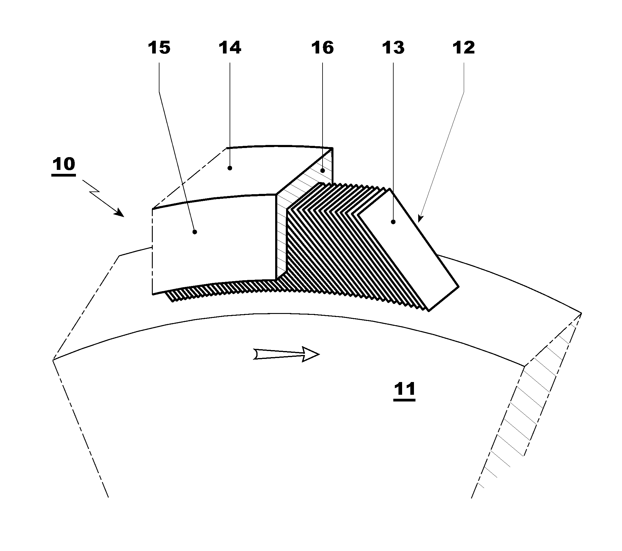
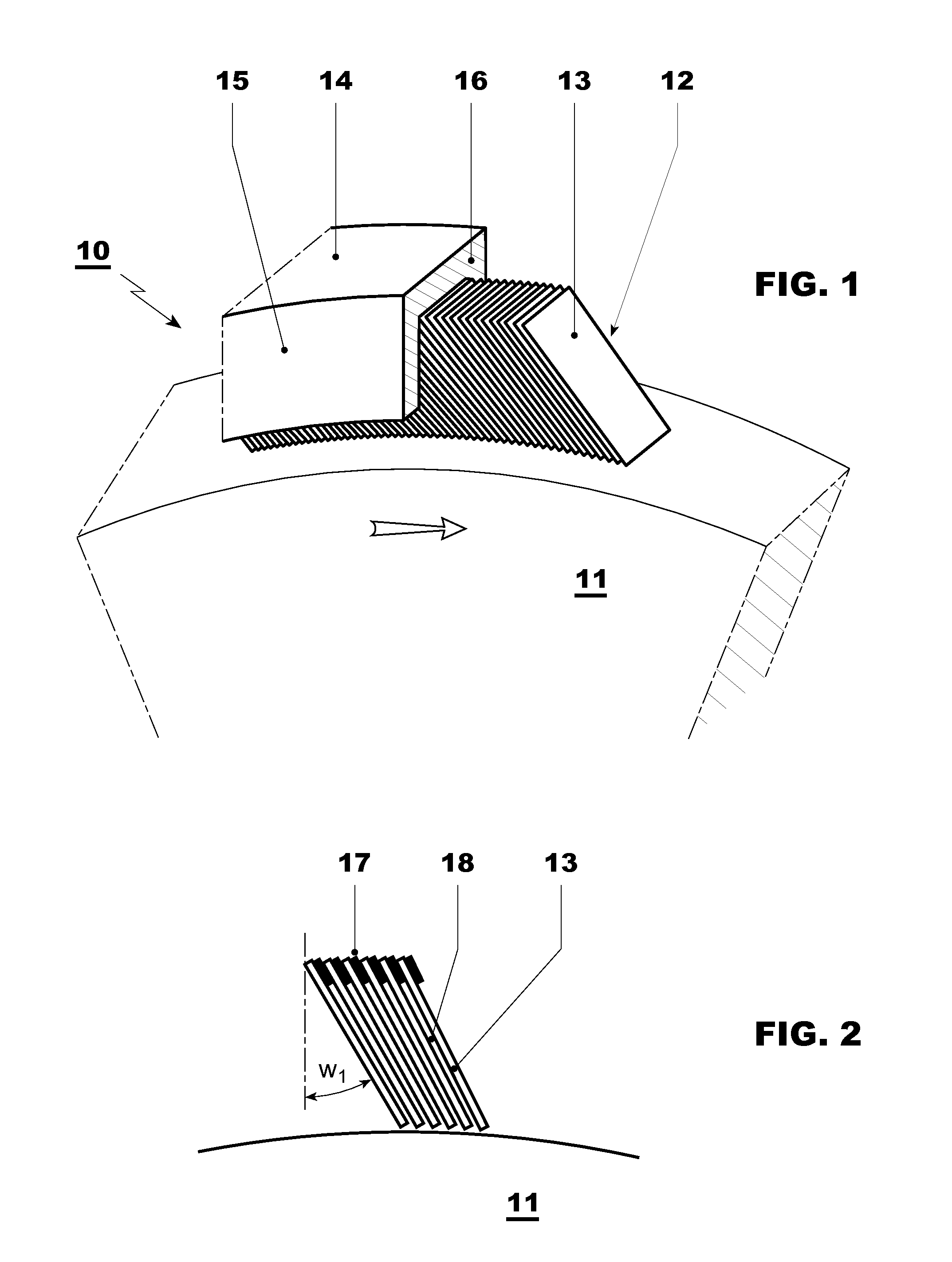
[0041]FIGS. 1 and 2 reproduce the closest prior art. In FIG. 1, in a perspective side view, the typical construction of a lamellar seal is shown, as is used for example in a gas turbine (10). The lamellar seal (12) seals a rotor shaft (11), which rotates in the direction of the arrow, of the gas turbine (10) against a casing (14). In the annular gap between the rotor shaft (11) and the casing (14), the lamellar seal (12) essentially includes a packet of thin lamellae (13) which are closely spaced apart from each other and arranged inside a carrier structure (15, 16). The lamellae (13) are oriented by their surface essentially parallel to the rotational axis of the turbine. As is apparent from FIG. 2, the lamellae (13) are inclined from the radial by an angle w1. Between the individual lamellae (13), a narrow gap or space (18) is formed in each case, which according to the prior art is established by spacer elements (17) which are arranged between the lamellae (13). In this case, the...


PUM


Abstract

A lamellar seal for sealing a shaft which rotates around an axis, especially in a gas turbine, includes a multiplicity of lamella (13) which are spaced one beneath the other, arranged in a concentric circle around the axis, and fixed in their position, wherein the lamellae (13) by their surfaces are oriented essentially parallel to the axis. The lamellar seal is improved by the fact that the lamellae (13) have formed-on structures (19, 20, 21) in each case for positioning and retaining the lamellae (13) in the lamellar seal (12), which include one or more laterally projecting support arms (19, 20, 21) which engage in complementarily formed recesses (25, 26) of the end plates (15, 16).

Description

[0001]This application claims priority under 35 U.S.C. §119 to German Application No. 102009015122.2, filed 31 Mar. 2009, the entirety of which is incorporated by reference herein.BACKGROUND[0002]1. Field of Endeavor[0003]The present invention relates to the field of turbomachines, especially to those turbomachines with large rotor diameters, such as stationary gas turbines or steam turbines, but also to jet engines. The present invention also relates to a lamellar seal around the rotating shaft of such a machine.[0004]2. Brief Description of the Related Art[0005]A gas turbine includes a rotor, upon which different stages with compressor blades and turbine blades are attached, and also a stator casing. The rotor is mounted at each end of the rotor shaft in bearings.[0006]Controlling the gas flow inside the gas turbine is of paramount importance with regard to both the functionality and the efficiency of the gas turbine. Of outstanding importance in this context is the prevention of ...

Claims


Application Information

Patent Timeline
IPC IPC(8): F01D25/00F16J15/16
CPCF01D11/001F05D2240/57F16J15/3292F05D2240/59
Inventor AMBROSY, GUNTERHOBEL, MATTHIASVOGT, ERNSTHAFNER, JOSEF
Owner ANSALDO ENERGIA SWITZERLAND AG
Why Eureka
Try Eureka