
Automated tissue staining system and reagent container

a tissue staining system and tissue staining technology, which is applied in the direction of instruments, liquid transfer devices, analysis using chemical indicators, etc., can solve the problems of large amount of reagent waste, large amount of reagent, etc., to achieve the effect of reagents, and reducing the number of reagents used in automatic staining apparatus

Inactive Publication Date: 2005-09-01
LAB VISION CORP
View PDF47 Cites 25 Cited by
  • Summary
  • Abstract
  • Description
  • Claims
  • Application Information

AI Technical Summary

Benefits of technology

The present invention provides apparatus and methods for staining tissue specimens using an autostainer. The invention includes a reagent container with a unique design and a removable drawer for holding reagent containers and slide racks. The staining apparatus also has a robotic delivery system and an optical reader for reading encoded staining protocol information and analyzing images. The invention allows for automated staining of tissue specimens with improved efficiency and accuracy.

Problems solved by technology

Reagents are expensive expendable commodities.
Conventional reagent containers are not configured to optimize the amount of reagent that the reagent probe successfully can withdraw and, thereby, to minimize the amount of reagent wasted.
However, one-dimensional bar codes capable of holding a complete set of reagent parameters are too large to be placed on the reagent containers commonly used in automatic staining apparatus.
Therefore, the lab technician compromises or otherwise disrupts the integrity of the controlled environment in the processing space when slides are added to a currently executing staining run.
Conventional automated staining devices cannot provide or export the protocol directly to a patient record database or laboratory information system so that, should a question arise regarding the protocol used to stain a specific tissue specimen, the complete association is readily available in a single database.

Method used


Image

  • Automated tissue staining system and reagent container
  • Automated tissue staining system and reagent container
  • Automated tissue staining system and reagent container

Examples


Embodiment Construction

[0027] To remedy the aforementioned deficiencies of conventional automated tissue staining devices, the present invention provides an apparatus for automatically staining tissue specimens carried by slides according to various staining protocols and a reagent container that significantly reduces the amounts of wasted reagents. As used hereinafter, the term “staining” includes, but is not limited to, reagent uptake, chemical reaction, localization (e.g., antigen-antibody associations), radioactive activation, and the like.

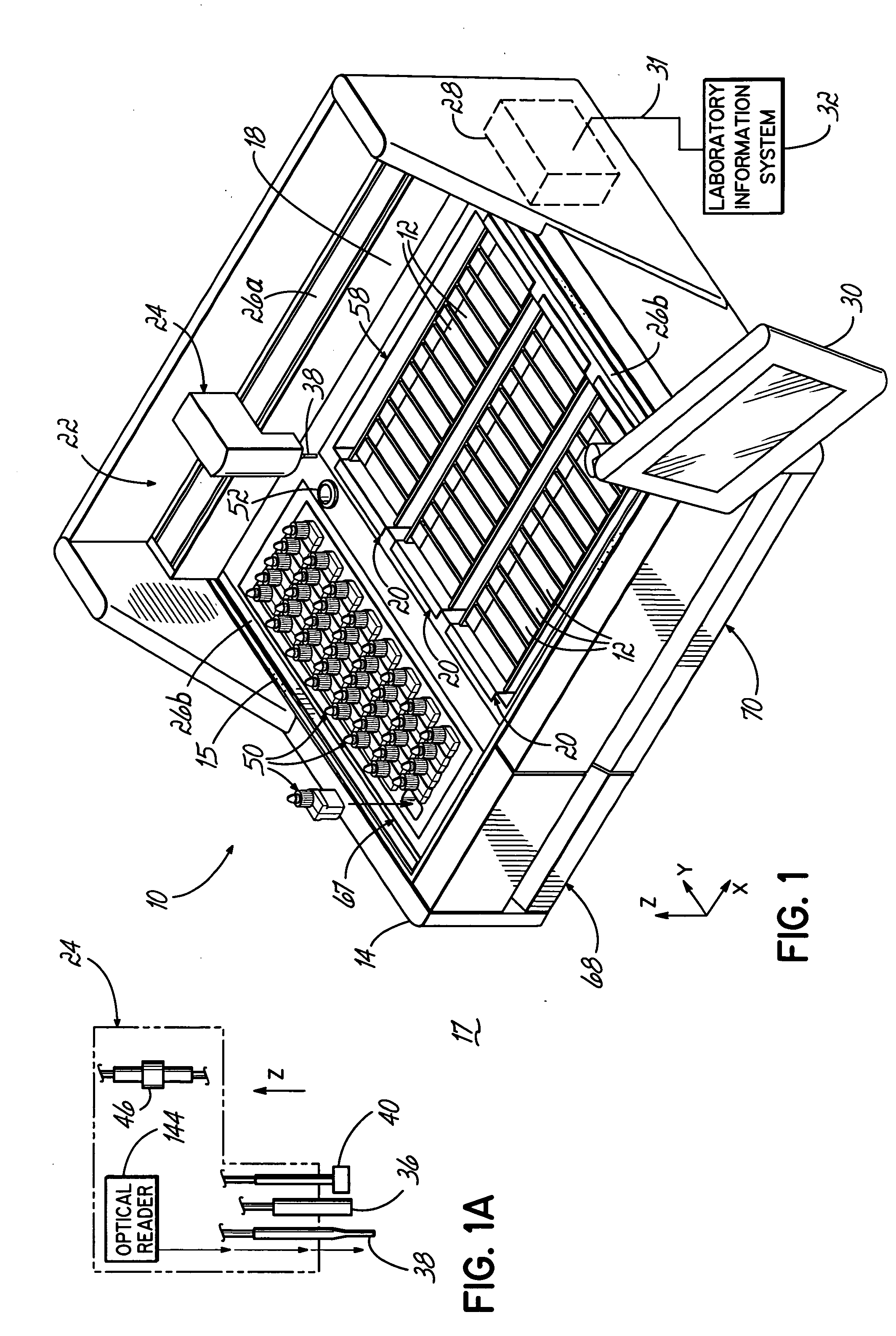
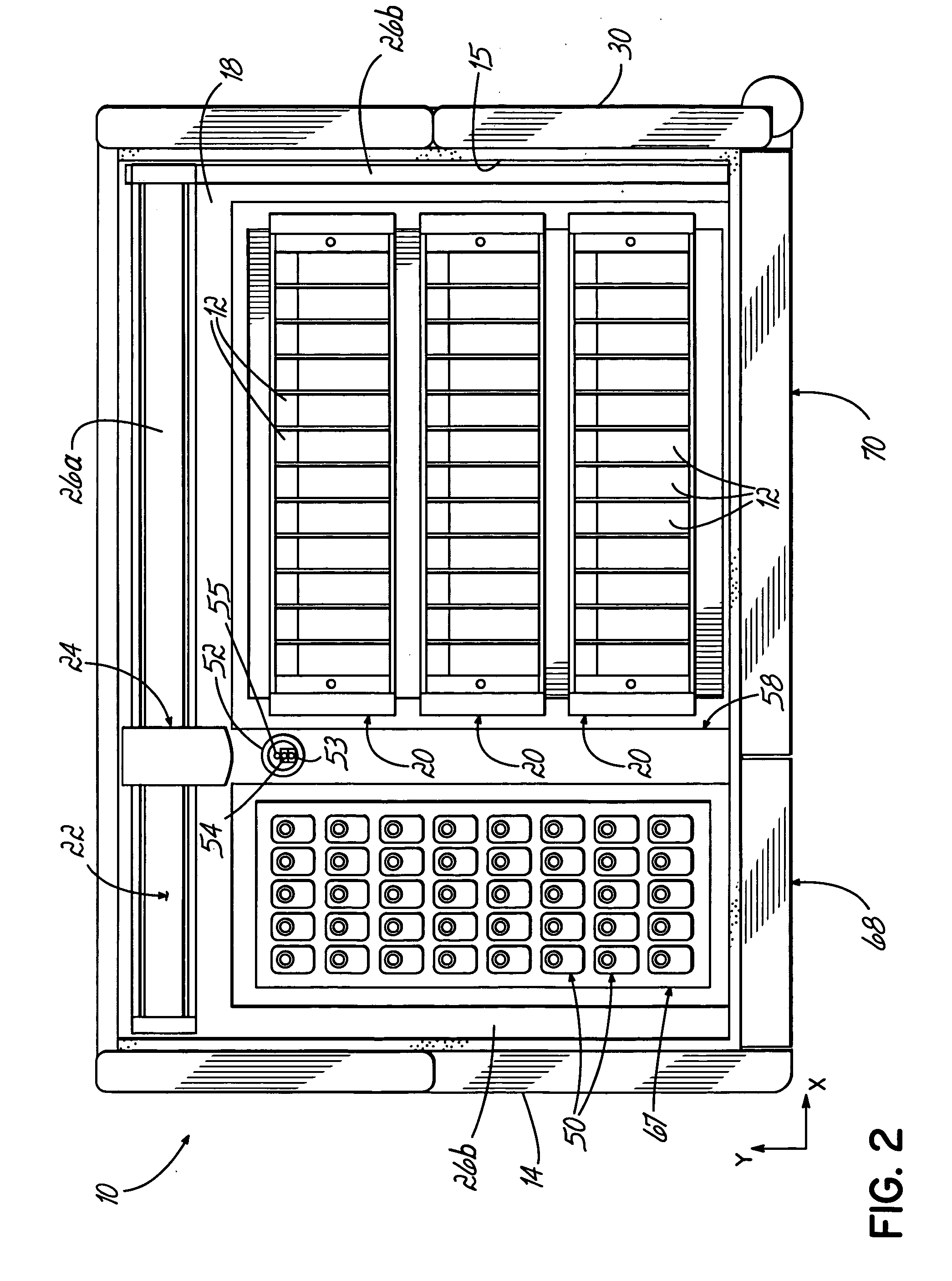
[0028] With reference to FIGS. 1, 2, and 3, the present invention comprises an automatic staining apparatus or autostainer 10 used for staining or otherwise reacting reagents with the cells of tissue specimens mounted on slides 12. The autostainer 10 includes a chassis 14 and a cover or lid 16 (FIG. 3), hinged along its rear horizontal edge, that collectively define a processing space 18 having a controlled environment, such as controlled humidity. The lid 16 isola...


PUM

PropertyMeasurementUnit
angleaaaaaaaaaa
volumeaaaaaaaaaa
volumeaaaaaaaaaa

Abstract

An automated staining system and a reagent container designed for use with the automated staining apparatus. The reagent container includes a reagent containment section capable of containing a volume of a reagent. The reagent containment section includes an upper wall and a base wall that are spaced apart along an axis. The base wall includes a well having a nadir that is aligned axially with an access opening in the upper wall so that a reagent probe entering the opening parallel to said axis will travel toward the nadir. In another aspect of the invention, the reagent container may include a two-dimensional data element containing reagent information. The staining apparatus may include one removable drawer for holding reagent containers and another removable drawer holding slides.

Description

[0001] This Is a Continuation-In-Part of U.S. application Ser. No. 09 / 994,458, filed Nov. 26, 2001 which is expressly incorporated by reference herein in its entirety.FIELD OF THE INVENTION [0002] The invention relates generally to an automated tissue staining system and reagent containers for use with the system. BACKGROUND OF THE INVENTION [0003] Laboratories routinely stain tissue specimens for the purpose of detecting and / or monitoring tissue abnormalities. An automated tissue staining system allows batch staining of large numbers of tissue specimens for subsequent examination. Automation of the staining process significantly reduces the time required to stain tissue specimens, reduces the incidence of human error incipient in manual staining, and allows processing parameters to be altered in an efficient manner. [0004] The staining process requires various types of reagents that are added to a slide carrying a tissue specimen. Reagents are expensive expendable commodities. In a...

Claims


Application Information

Patent Timeline
Patent Type & Authority Applications(United States)
IPC IPC(8): B65D1/02B65D47/06B65D51/18B67D7/72G01N1/31G01N35/00G01N35/10
CPCB65D1/0223B65D47/06B65D51/18B65D2203/04B65D2251/0015B65D2251/0087G01N2035/0498G01N1/312G01N35/0099G01N35/1002G01N2035/00752G01N2035/00881B65D2501/0081
Inventor TSEUNG, KEN K.RHETT, NORMAN K.TAKAYAMA, GLENN K.WONG, WAI BUNYUEN, DELIA P.
Owner LAB VISION CORP
Learn More