
Decision feedback equalizer with dynamic feedback control

a feedback equalizer and dynamic feedback technology, applied in pulse manipulation, pulse technique, baseband system details, etc., can solve the problems of large performance loss, difficult and sometimes unfeasible to design precisely symbol-spaced, and flat group delay filter, so as to optimize the recovery of data signals

Inactive Publication Date: 2005-09-01
MARVELL ASIA PTE LTD
View PDF14 Cites 32 Cited by
  • Summary
  • Abstract
  • Description
  • Claims
  • Application Information

AI Technical Summary

Benefits of technology

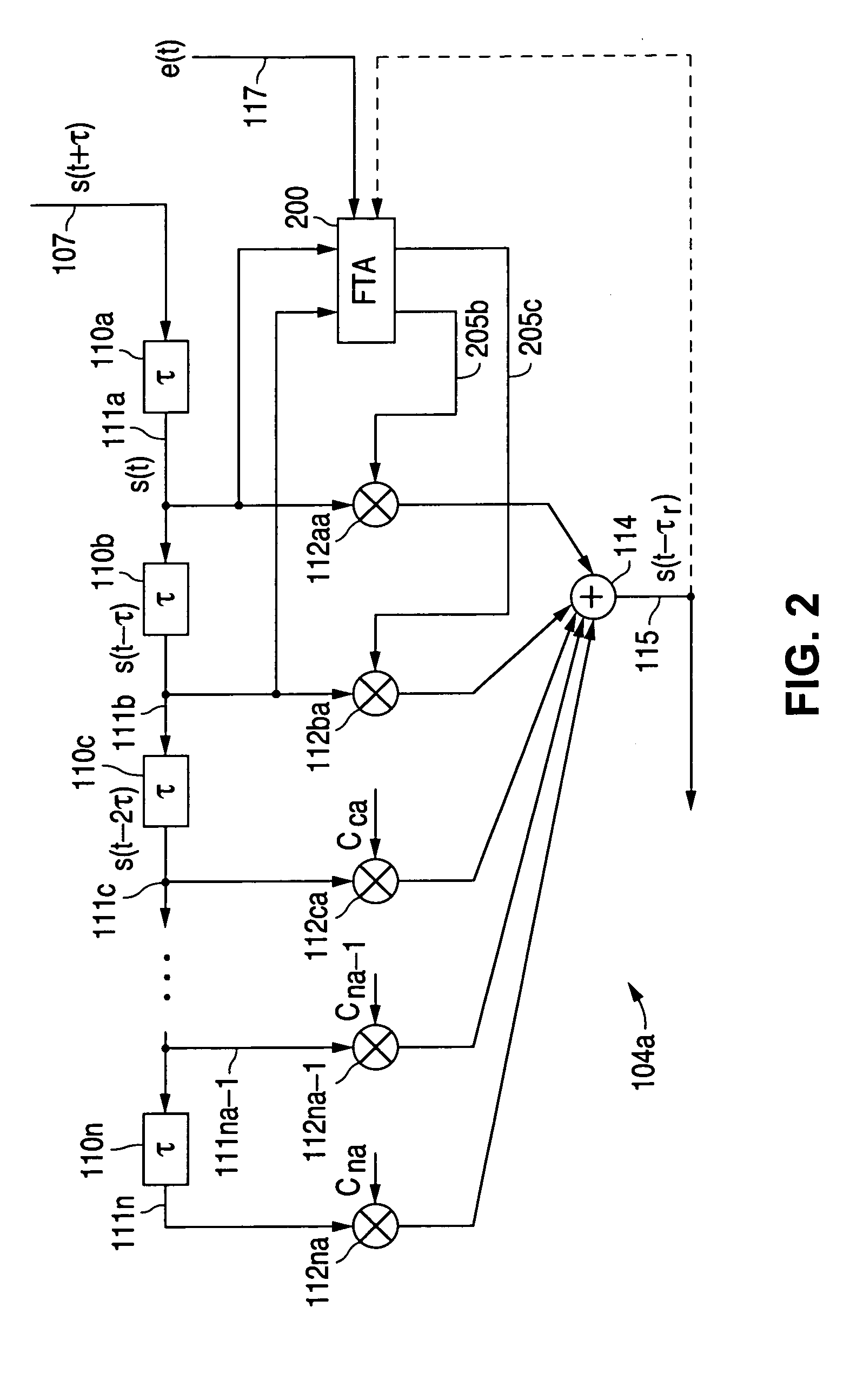
[0010] A decision feedback equalizer with dynamic feedback control for use in an adaptive signal equalizer in accordance with the presently claimed invention includes timing within the decision feedback loop that is dynamically controlled to optimize recovery of the data signal by the output signal slicer.

Problems solved by technology

When continuous-time feedback is considered, a number of difficulties are encountered.
For example, it is difficult and sometimes unfeasible to design precisely symbol-spaced, flat group delay filters.
If the total group delay on the feedback path for canceling successive past symbols is even slightly different from the corresponding symbol period, the performance loss can be substantial.
Further when an equalizer with fractionally-spaced feedback taps is used, independent LMS adaptation of the successive feedback taps fails because of the strongly correlated nature of the fractional tap-spaced feedback data.

Method used


Image

  • Decision feedback equalizer with dynamic feedback control
  • Decision feedback equalizer with dynamic feedback control
  • Decision feedback equalizer with dynamic feedback control

Examples


Embodiment Construction

[0038] The following detailed description is of example embodiments of the presently claimed invention with references to the accompanying drawings. Such description is intended to be illustrative and not limiting with respect to the scope of the present invention. Such embodiments are described in sufficient detail to enable one of ordinary skill in the art to practice the subject invention, and it will be understood that other embodiments may be practiced with some variations without departing from the spirit or scope of the subject invention.

[0039] Throughout the present disclosure, absent a clear indication to the contrary from the context, it will be understood that individual circuit elements as described may be singular or plural in number. For example, the terms “circuit” and “circuitry” may include either a single component or a plurality of components, which are either active and / or passive and are connected or otherwise coupled together to provide the described function....


PUM


Abstract

A decision feedback equalizer with dynamic feedback control for use in an adaptive signal equalizer. Timing within the decision feedback loop is dynamically controlled to optimize recovery of the data signal by the output signal slicer.

Description

RELATED APPLICATIONS [0001] This is a continuation-in-part of U.S. patent application Ser. No. 10 / 768,408, filed Jan. 30, 2004, which is a continuation-in-part of U.S. patent application Ser. No. 10 / 322,024, filed Dec. 17, 2002, which is a continuation-in-part of U.S. patent application Ser. No. 10 / 290,571, filed Nov. 8, 2002.BACKGROUND OF THE INVENTION [0002] 1. Field of the Invention [0003] The present invention relates to signal transmission and detection, and in particular, to techniques for compensating for signal distortions caused by signal dispersion and nonlinearities within the signal transmission media. [0004] 2. Description of the Related Art [0005] Signal processing architectures for intersymbol interference (ISI) equalization as used for communications transmission and / or storage systems may be divided into two categories: discrete-time architecture and continuous-time architecture. Discrete-time architectures, commonly used in current systems, use a sampled approach t...

Claims


Application Information

Patent Timeline
Patent Type & Authority Applications(United States)
IPC IPC(8): H03H21/00H04L25/03
CPCH03H21/0012H03H2021/0096H04L25/03057H04L2025/03611H04L25/0307H04L2025/0349H04L2025/03509H04L25/03063
Inventor IBRAGIMOV, EDEMYU, QIANCHOUDHARY, PRASHANT
Owner MARVELL ASIA PTE LTD
Learn More