
Versatile modular programmable power system for wireline logging

a modular, wireline technology, applied in the direction of instruments, surveying, borehole/well accessories, etc., can solve the problems of increasing asset costs, increasing costs and size, cumbersome and bulky power supply systems,

Inactive Publication Date: 2005-09-01
SCHLUMBERGER TECH CORP
View PDF6 Cites 19 Cited by
  • Summary
  • Abstract
  • Description
  • Claims
  • Application Information

AI Technical Summary

Benefits of technology

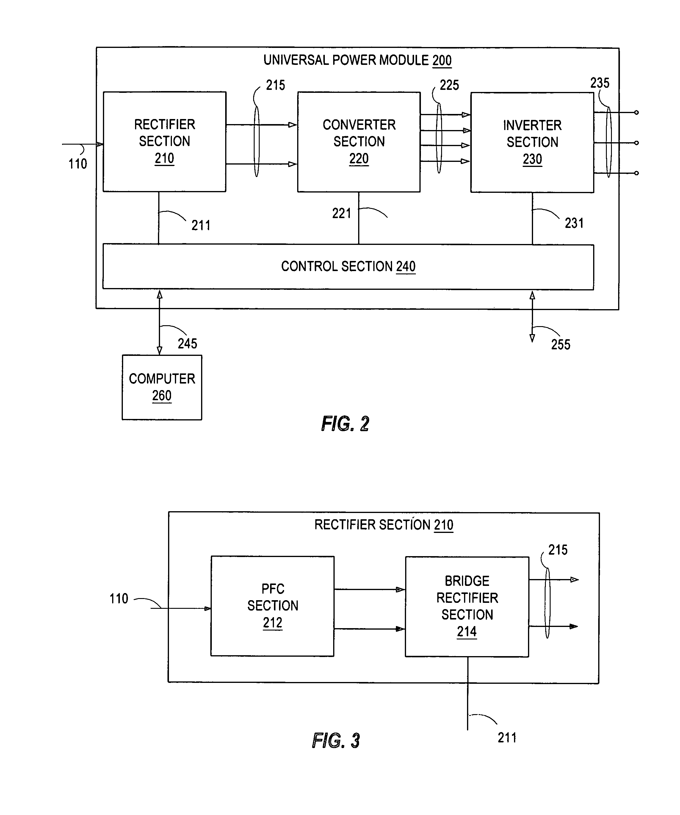
[0013] The foregoing need is addressed by the present invention. According to one form of the invention, a method and system for providing power to a wireline logging system includes a rectifier section operable to receive an alternating current (AC) input signal and generate a first direct current (DC) power signal as an output. A converter section cascadedly coupled to the rectifier section converts the first DC power signal to a second DC power signal thereby causing the second DC power signal to be floated with respect to the first DC power signal and a ground. An inverter section cascadedly coupled to the converter section is operable to generate an output power signal providing power to a load in response to receiving the second DC power signal. A control section is coupled to the rectifier section, the converter section, the inverter section and a communications link. The communications link is operable to receive information describing waveforms for the output power signal. The control section is operable to receive the information and control a corresponding section to generate the waveforms in response to receiving the information.

Problems solved by technology

The traditional approach to providing power thus results in cumbersome and bulky power supply systems having different types of power sources to manage and maintain.
Spare parts requirement to stock the disparate types of generators increase asset costs.
Designing for redundancy to accommodate failures further adds to the costs and size.

Method used


Image

  • Versatile modular programmable power system for wireline logging
  • Versatile modular programmable power system for wireline logging
  • Versatile modular programmable power system for wireline logging

Examples


Embodiment Construction

[0026] In the following detailed description of the preferred embodiments, reference is made to the accompanying drawings illustrating embodiments in which the invention may be practiced. It should be understood, however, that the drawings and detailed description are not intended to limit the invention to the particular form disclosed, but on the contrary, the intention is to cover all modifications, equivalents and alternatives falling within the spirit and scope of the present invention as defined by the appended claims.

[0027]FIG. 2 is a block diagram of selected elements of a universal power module 200 according to one embodiment of the invention. In the depicted embodiment, the universal power module 200 includes: [0028] a) a rectifier section 210 operable to receive the AC power signal 110 and generate a first direct current (DC) power signal 215 as an output; [0029] b) a converter section 220 cascadedly coupled to the rectifier section 210. The converter section 220 is opera...


PUM


Abstract

A method and system for providing power to a wireline logging system includes a rectifier section operable to receive an AC input signal and generate a first DC power signal as an output. A converter section cascadedly coupled to the rectifier section converts the first DC power signal to a second DC power signal. An inverter section cascadedly coupled to the converter section is operable to generate an output power signal providing power to a system in response to receiving the second DC power signal. A control section is coupled to the rectifier section, the converter section, the inverter section and a communications link. The communications link is operable to receive information describing waveforms for the output power signal. The control section is operable to receive the information and control a corresponding section to generate the waveforms in response to receiving the information.

Description

CROSS-REFERENCE TO RELATED APPLICATIONS [0001] Applicants hereby claim the benefit of U.S. Provisional Application Ser. No. 60 / 549,013 filed Mar. 1, 2004 and entitled “VERSATILE MODULAR PROGRAMMABLE POWER SYSTEM FOR WIRELINE”, which provisional application is incorporated herein for all purposes.BACKGROUND OF THE INVENTION [0002] 1. Field of the Invention [0003] The present invention relates to wireline logging systems for subsurface resource drilling, and more particularly relates to providing power for wireline logging. [0004] 2. Related Art [0005] The exploration for subsurface resources such as hydrocarbons including oil and gas, minerals and water, typically requires various techniques for determining the characteristics of geological formations. Many characteristics, such as the hydrocarbon volume, resistivity, porosity, lithology, and permeability of a formation, may be deduced from certain measurable quantities associated with the geological formations. It is a well-known te...

Claims


Application Information

Patent Timeline
Patent Type & Authority Applications(United States)
IPC IPC(8): E21B47/00H02J3/00H02M5/458
CPCE21B47/00H02M2001/0077H02M5/458H02M1/0077
Inventor HERNANDEZ-MARTI, RAMONMARTINEZ, GILBERT R.MAYHUGH, TERRY L.
Owner SCHLUMBERGER TECH CORP
Learn More