
Image processor and image processing program for applying image processing to input data and transferring the same to print engine

Active Publication Date: 2005-09-01
RISO KAGAKU CORP
View PDF3 Cites 3 Cited by
  • Summary
  • Abstract
  • Description
  • Claims
  • Application Information

AI Technical Summary

Benefits of technology

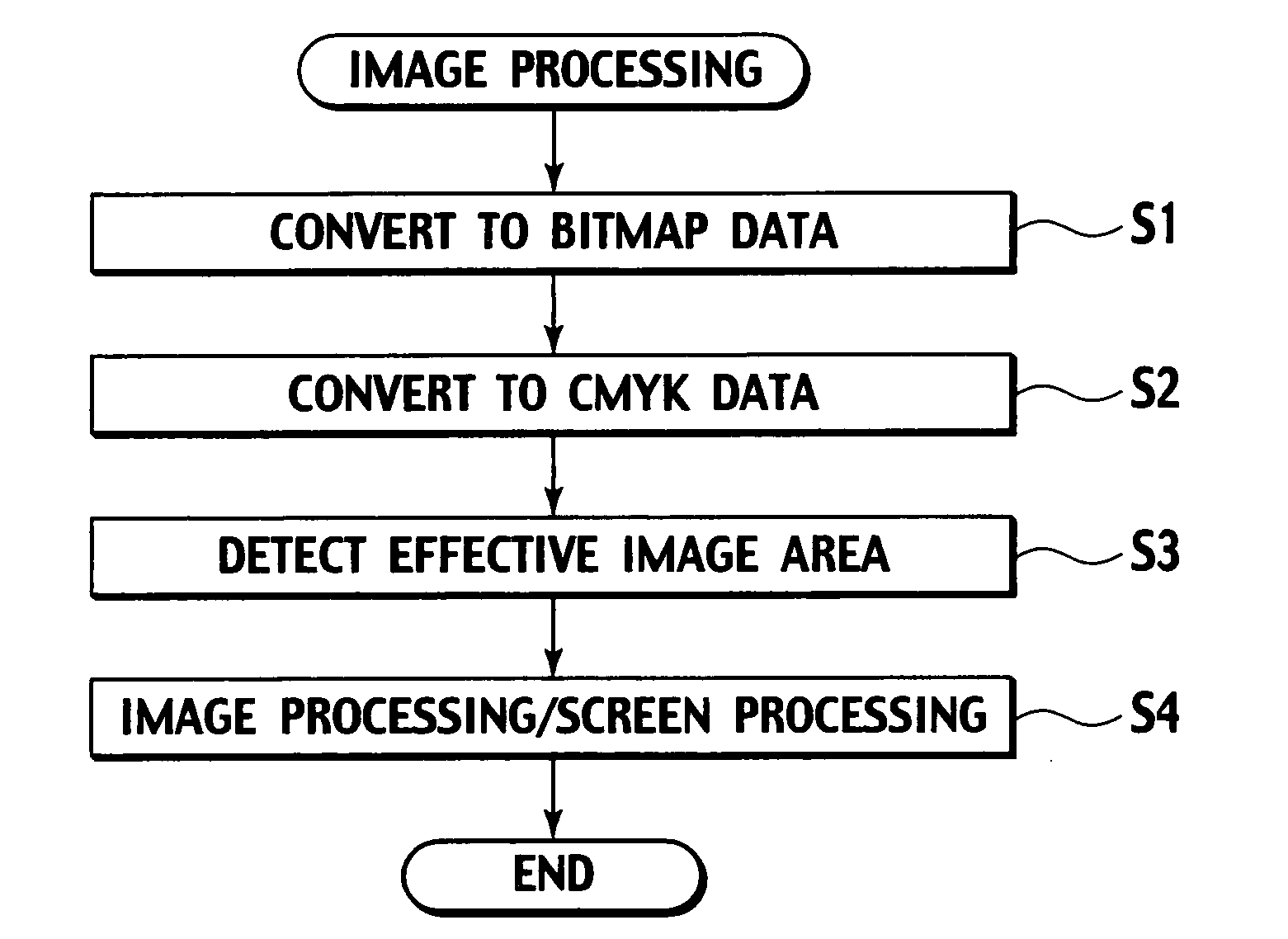
[0006] According to the above configuration of the present invention, the image processing is subjected only to the image data in the effective image area, which reduces image processing time. Furthermore, only the image data in the effective image area is transferred to the print engine together with the position and size information of the effective image area, which also reduces data transfer time. That is, the image processor and the image processing program according to the present invention can reduce both the image processing time and the data transfer time, and consequently reduce printing time of image data.
[0007] When the image data is converted to CMYK format, the effective image area is preferably detected from each of CMYK color planes. In this case, it is desirable to determine an intermediate coordinate system that is common to all the CMYK color planes and to transfer to the print engine the position and size information of each effective image area calculated based on the intermediate coordinate system together with the position information of the origin of the determined intermediate coordinate system. According to this configuration, by only changing the position of the origin of the intermediate coordinate system, the image printing positions of all the CMYK color planes can be adjusted in vertical and lateral directions with the positional relationship among these color planes maintained securely.
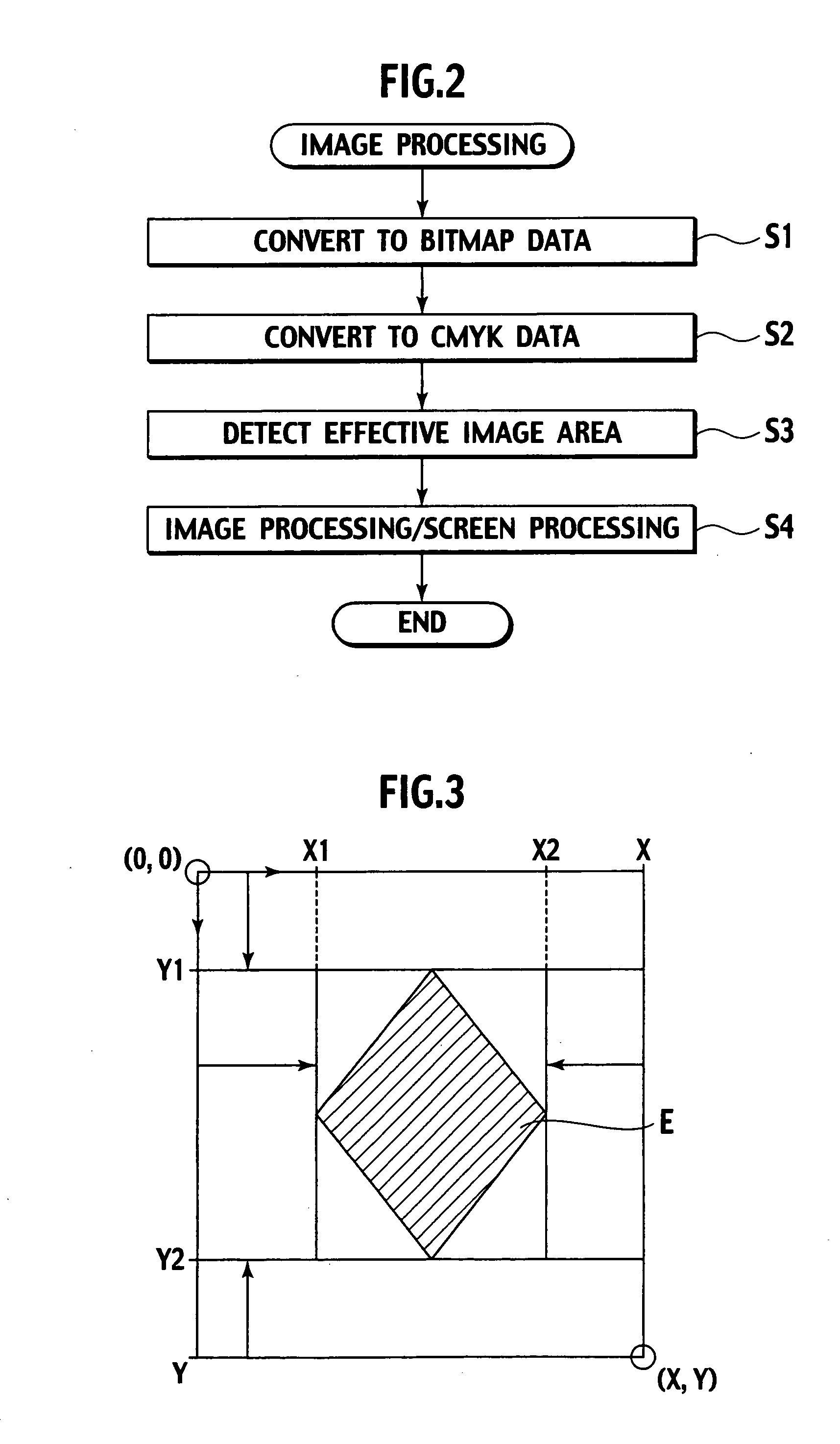
[0008] Moreover, in order to detect the effective image area, it is desirable to first search transverse lines of image data in up and down directions so as to detect one transverse line on which an upper end of the effective image area is positioned and another transverse line on which a lower end of the effective image area is positioned, and next to search longitudinal lines running between the detected two transverse lines in left and right directions so as to detect one longitudinal line on which a left end of the effective image area is positioned and another longitudinal line on which a right end of the effective image area is positioned. According to this configuration, the effective image area can be detected efficiently even when an effective image is deviated either upward or downward.

Problems solved by technology

Furthermore, only the image data in the effective image area is transferred to the print engine together with the position and size information of the effective image area, which also reduces data transfer time.

Method used


Image

  • Image processor and image processing program for applying image processing to input data and transferring the same to print engine
  • Image processor and image processing program for applying image processing to input data and transferring the same to print engine
  • Image processor and image processing program for applying image processing to input data and transferring the same to print engine

Examples


Embodiment Construction

[0016] The present invention is applicable to an image processor 1 which applies image processing to image data input from an application and transfers the processed image data to a print engine which forms an image on a print sheet. With reference to the accompanying drawings, a configuration and operations of the image processor 1 according to an embodiment of the present invention will be described in detail below.

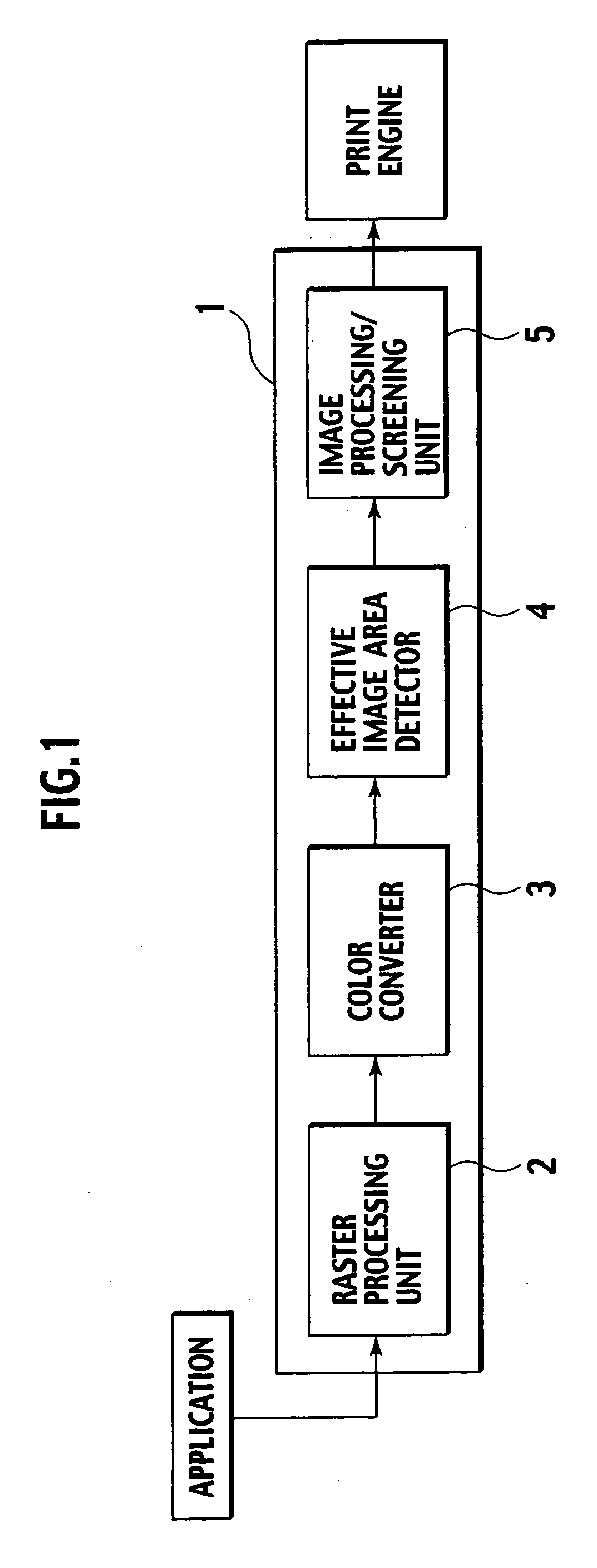
[0017] The image processor 1 according to the embodiment of the present invention is provided in an image forming apparatus such as a full color printer, and mainly includes, as shown in FIG. 1, a raster processing unit 2, a color converter 3, an effective image area detector 4, and an image processing / screening unit 5. The image processor 1 applies image processing to image data input from an application, and then transfers the processed image data to a print engine which forms an image on a print sheet.

[0018] Each component in the image processor 1 may be configured...


PUM


Abstract

The effective image area detector 4 detects an effective image area within image data subjected to color conversion, and an image processing / screening unit 5 applies image processing to image data in the effective image area and transfers the processed image data in the effective image area to a print engine together with position and size information of the effective image area. This reduces image processing time and data transfer time to the print engine, thereby reducing printing time of image data.

Description

BACKGROUND OF THE INVENTION [0001] The present invention relates to an image processor and an image processing program for applying image processing to input data and transferring the data to a print engine. More particularly, the present invention relates to a technique for reducing the time for printing input data by reducing image processing time and data transfer time to a print engine. [0002] Generally in full color printers, in response to an input of RGB data from an application program (hereinafter referred to as “an application”), an internal controller (data generating unit) converts the RGB data to raster data (bitmap data), which is followed by color conversion to CMYK data. As disclosed in Japanese Patent Application Laid-Open Nos. H6-238950 and H9-83811, the internal controller subsequently converts the CMYK data to data having a small number of gradations consistent with the printing capability of a print engine by executing image processing such as error diffusion an...

Claims


Application Information

Patent Timeline
IPC IPC(8): G06F3/12G06T1/00B41J5/30H04N1/46H04N1/58H04N1/60
CPCH04N1/58
Inventor YONEOKA, HIDEHARU
Owner RISO KAGAKU CORP
Learn More