
Networked personal security system

a personal security and network technology, applied in the field of networked personal security systems, can solve the problems of inability to track the location of patients, require manual activation of panic buttons, and inability of wearers to manually activate systems, so as to preserve the ability to transmit and minimize the current dependency of finding.

Inactive Publication Date: 2005-09-01
PR NEWSWIRE
View PDF99 Cites 7 Cited by
  • Summary
  • Abstract
  • Description
  • Claims
  • Application Information

AI Technical Summary

Benefits of technology

"The present invention is a personal alarm system that is affordable, portable, and compatible with a comprehensive security system. The device can be worn or carried by the user and can be activated at any time. It sends a signal to a remote monitoring station or can automatically activate in case of an emergency. The device identifies the user and their location, and can also collect additional data and store it in a database. The system uses beacons or GPS technology to track the user's location. The device is useful in aircraft applications and can activate the security system in real-time. The invention provides a portable and effective solution for personal safety and security in various settings."

Problems solved by technology

A major drawback to this system is the inability to track the location of a patient.
Another drawback is the requirement that the panic button be manually activated in all circumstances.
In certain situations, it may be impossible for the wearer to manually activate the system, rendering the panic system ineffective.
To date, no known devices provide such features and capability.
While each of the prior art devices address certain location issues, none of the known devices provides an affordable, comprehensive personal signaling and locating device.

Method used


Image

  • Networked personal security system
  • Networked personal security system
  • Networked personal security system

Examples


Embodiment Construction

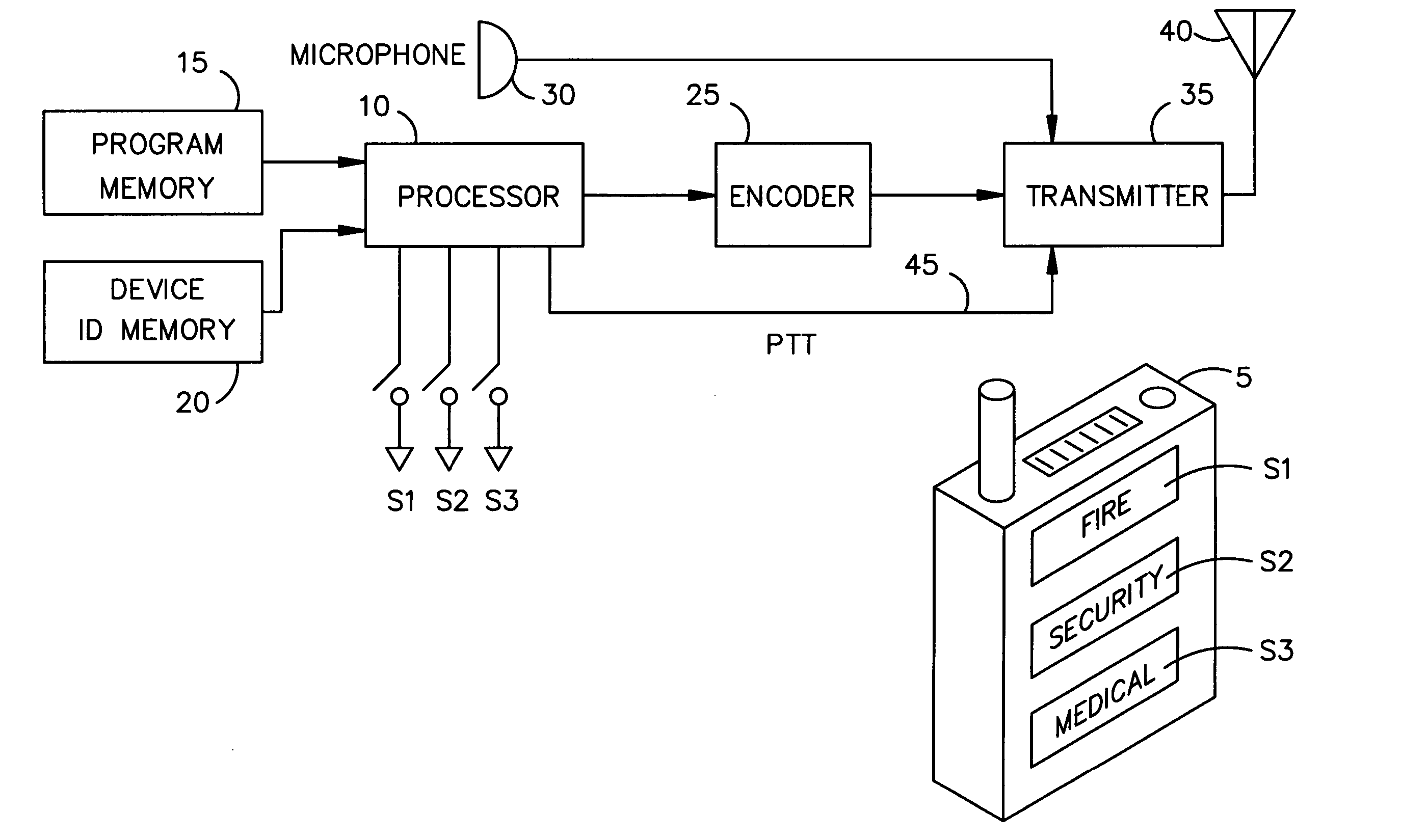
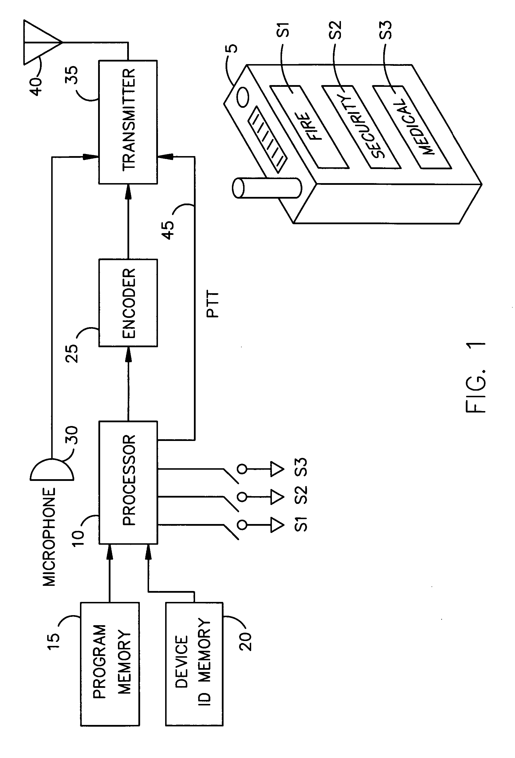
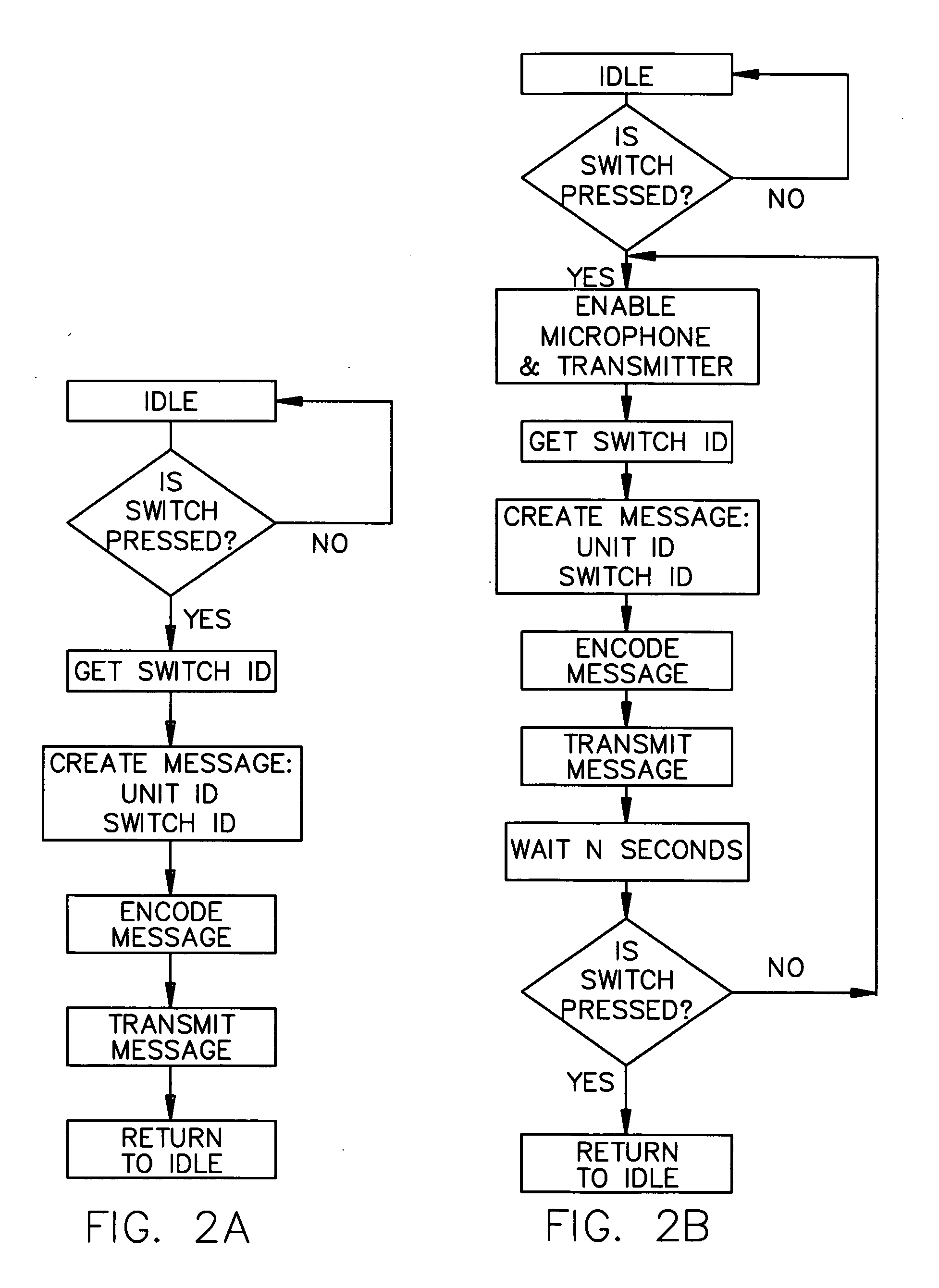
[0050]FIGS. 1-3 depict a basic embodiment of the system that does not included encoded location information. This application is particularly well suited for confined environments such as aircraft and the like, where the location of the person sending the signal is not as critical as in large installations such as a high school campus. In its simplest form, the alarm unit 5 of FIG. 1 comprises a simple panic button, which is a radiator that transmits a coded signal to the closest receiver via the antenna 40, with the receivers of FIG. 3 being conveniently located and connected to the network. Receivers can be integrated into other devices, such as wall clock appliances, thermostats, smoke detectors, motion detectors, and the like in the room or facility where the alarm unit is to be used. The transmitter radiator may comprise any of a number of signal generating protocols, such as, by way of example: RF (a potential location problem for certain applications in that it goes through w...


PUM


Abstract

A personal alarm system can be worn or carried by the user, may be activated at any time by the user and / or may be automatically activated to send a signal to any remote monitoring station on the network. The device identifies the user as well as the user's location within the monitored area. The alarm-sending unit is designed to fit within a box the size of a small cell phone or pager. The unit includes an ID memory for identifying the user, is programmable and has an on-board processor for generating a signal to a wireless transmitter for sending the signal to a to a local receiver for inputting the signal onto the network. A centralized, networked RF receiver is used with the personal alarm unit and one or more of these RF receivers may be installed in order to provided adequate coverage of the monitored area. The signals generated by the personal alarm are received by the RF receiver(s) and decoded, whereupon the system processor assembles a message, packetizes it as necessary, and sends it to one or more monitoring stations via the intervening network and network interface. The signals may be digitized where desired. A beacon generator may be used to identify location of the portable unit. The system may also employ a GPS generator to identify location.

Description

[0001] The invention is a continuation of co-pending patent application Ser. No. 09 / 974,337, filed Oct. 10, 2001 “Networked Personal Security System.” The subject invention is generally related to personal security alarms or panic button devices and is specifically directed to a personal alarm system having network communication capability whereby the user can generate a signal to a remote location from any monitored area.BACKGROUND OF THE INVENTION [0002] 1. Field of the Invention [0003] 2. Description of the Prior Art [0004] There are numerous devices that allow an individual to send a panic signal to a remote location in order to seek assistance when certain events occur. For example, many semi-invalid medical patients will wear a panic button as pendant around their neck, with the panic button adapted to be manually pushed in order to signal a medical emergency. The button device then transmits a signal to a remote monitoring station for initiating a response. Basically, the dev...

Claims


Application Information

Patent Timeline
Patent Type & Authority Applications(United States)
IPC IPC(8): G08B25/01
CPCG08B25/016G08B21/0269G08B25/006
Inventor MONROE, DAVID A.
Owner PR NEWSWIRE
Learn More