
Phosphor, light source and LED

a technology of phosphor and light source, applied in the direction of discharge tube/lamp details, discharge tube luminescent screens, discharge tubes/lamp details, etc., can solve the problem of not producing high light emission, and achieve the effect of improving the luminance of visible light or white light, not only the emission efficiency of the light emitting portion, and the emission efficiency of the phosphor

Inactive Publication Date: 2005-09-01
NICHIA CORP
View PDF28 Cites 187 Cited by
  • Summary
  • Abstract
  • Description
  • Claims
  • Application Information

AI Technical Summary

Benefits of technology

[0012] With respect to the above-described LED and light source which emit visible light or white light by a combination of a light emitting portion which emits blue or ultraviolet light and a phosphor which has an excitation band corresponding to light of the ultraviolet-blue wavelength region generated from the light emitting portion, it is strongly demanded to improve not only the emission efficiency of the light emitting portion but also the emission efficiency of the phosphor, in order to improve luminance of the visible light or white light.
[0014] In the case that the phosphor is used as a phosphor for a white LED, luminance of the entire white LED is improved by the emission efficiency of the phosphor, so that a phosphor which emits light with better efficiency with respect to the emission wavelength of the light emitting element has been demanded.
[0015] For example, an excitation band of YAG:Ce based yellow phosphor is in an efficient excitation range when emitting light by blue light of a light emitting element of an LED, and thus it can produce good yellow light emission. However, when emitting light by ultraviolet light of a light emitting element of an LED, it deviates from the excitation range, so that it cannot produce high light emission.
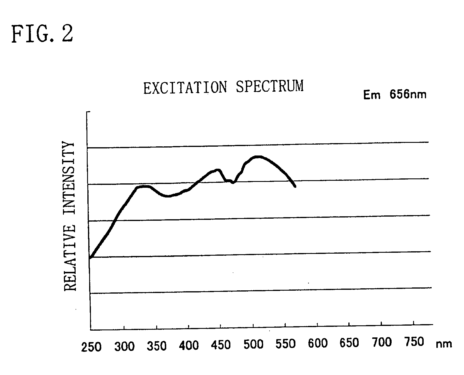
[0017] The present invention is made in view of the above-described situation, and an object thereof is to provide a phosphor with high efficiency having an excitation band corresponding to light of the ultraviolet-visible (300-550 nm) wavelength region emitted from a light emitting element which emits blue or ultraviolet light.
[0018] As a result of study on host material compositions of various phosphors with respect to the above-described object, the inventors of the present invention devised a phosphor with higher efficiency and an excellent light emitting characteristic, which has a new host material composition.
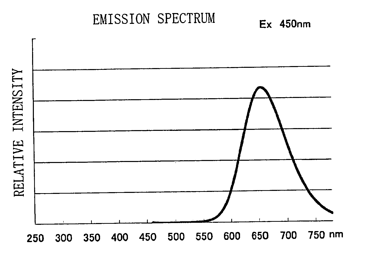
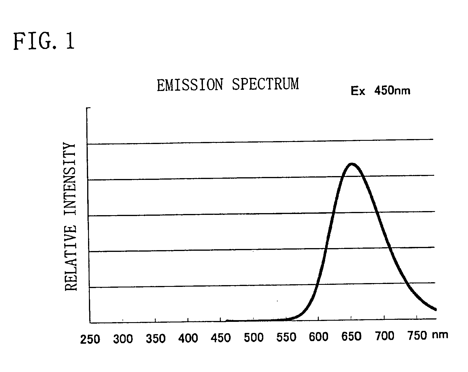
[0045] The phosphor represented: by a general formula M-A-B—N:Z according to the first to the eleventh aspect has an excitation band corresponding to ultraviolet-blue light (wavelength region of from 300 to 550 nm) emitted by a light emitting element which emits blue or ultraviolet light, and emits light with high efficiency. Therefore, by combining the phosphor with a light emitting portion which emits the ultraviolet-blue light, an LED, a light source and a lighting unit of monochromatic light or white light with high efficiency and high luminance can be obtained.

Problems solved by technology

However, when emitting light by ultraviolet light of a light emitting element of an LED, it deviates from the excitation range, so that it cannot produce high light emission.

Method used


Image

  • Phosphor, light source and LED
  • Phosphor, light source and LED
  • Phosphor, light source and LED

Examples


example 1

[0081] Commercially available Ca3N2 (2N), AlN (3N), Si3N4 (3N), and EU2O3 (3N) were prepared, and respective raw materials were weighed so that the mol ratio of respective elements becomes Ca:Al:Si:Eu=0.985:3:1:0.015 and mixed using a mortar inside a glove box under a nitrogen atmosphere. The mixed raw materials were heated to 1500° C. by a heating rate of 15° C. / min in a nitrogen atmosphere, retained and fired at 1500° C. for three hours, and cooled down thereafter from 1500° C. to 200° C. for an hour to obtain a phosphor of the composition formula Ca0.985SiAlN3:Eu0.015. Results of analysis of the obtained phosphor powder are shown in Table 1.

[0082] The average particle size (D50) of the obtained phosphor was 4.65 μm, and the specific surface area thereof was 1.13 m2 / g, and 2.2% of the total weight was occupied by oxygen as an impurity.

TABLE 1AverageparticleSpecificCaAlSiNEuOsizesurface(%)(%)(%)(%)(%)(%)Others(D50)areaCa0.985AlSiN3: Eu0.01527.320.519.229.21.462.20.14.65 μm1.13 m...

example 2

[0088] In Example 2, the phosphor according to the present invention having a composition formula CamSiAlN3:Eu was used to measure the luminescence intensity depending on concentration of the activator element Z.

[0089] When producing a measurement sample, addition amounts of Ca and Eu were adjusted so that the concentration of the activator Eu has a relationship of m+z=1 with Ca.

[0090] Results of the measurement will be described with reference to FIG. 3. Here, in FIG. 3, luminescence intensity of the phosphor of the present invention is taken on the vertical axis, and a value of Eu / (Eu+Ca), which is a compounding ratio of Ca and Eu, is taken on the horizontal axis. Note that luminescence intensity when Eu / (Eu+Ca)=0.015 is set as 100%. Then, results of adjusting the value of Eu / (Eu+Ca) from 0.0015 to 0.06 are shown. Note that light having a wavelength of 450 nm was, used for excitation.

[0091] As is clear from the results in FIG. 3, the luminescence intensity first rises with incr...

example 3

[0093] On an LED of ultraviolet light having a nitride semiconductor as a light emitting portion, the phosphor obtained according to the present invention, a commercially available blue phosphor (BAM:Eu), and a commercially available green phosphor (ZnS:Cu, Al) were applied, and the LED of ultraviolet light was illuminated. Then, the respective phosphors emitted light by light from the LED, and an LED which appears to be white when visually observed due to a spectrum of emission wavelength was obtained.

[0094] Further, on an LED of blue light having a nitride semiconductor as a light emitting portion, the phosphor obtained in the present invention and a commercially available yellow phosphor (YAG:Ce) were applied, and the LED of blue light was illuminated. Then, the respective phosphors emitted light by light from the LED, and a reddish LED having a low color temperature when visually observed was obtained.


PUM


Abstract

A phosphor with high efficiency having an excitation band corresponding to light of the ultraviolet-visible (300 to 550 nm) wavelength region emitted from a light emitting portion which emits blue or ultraviolet light is provided. A nitride of Ca, a nitride of Al, a nitride QfSi, and an oxide of Eu are prepared, and respective raw materials are weighed so that a mol ratio of respective elements becomes Ca:Al:Si:Eu=0.985:3:1:0.015, mixed under a nitrogen atmosphere, and thereafter fired at 1500° C. in a nitrogen atmosphere to thereby produce a phosphor having a composition formula Ca0.985SiAlN3:Eu0.015.

Description

BACKGROUND OF THE INVENTION [0001] 1. Field of the Invention [0002] The present invention relates to a phosphor used in a display device such as an LED, CRT, PDP, FED, and EL, and a lighting unit such as a vacuum fluorescent display (VFD) and fluorescent lamp, the phosphor being particularly suitable for an LED, a light source, and a lighting unit each of which has a light emitting portion of ultraviolet-blue light or the like and emits visible or white light. [0003] 2. Description of the Related Art [0004] An LED, a light source and a lighting unit are known, which emit white light by a combination of a light emitting element which emits blue or ultraviolet light and a phosphor which has an excitation band in the ultraviolet-blue wavelength region generated from the light emitting element. [0005] As the phosphor used in the LED and the like, Y2O2S:Eu, La2O2S:Eu, 3.5MgO.0.5MgF2.GeO2:Mn, and (La, Mn, Sm)2O2S .Ga2O3 are known as a red phosphor, ZnS:Cu,Al, SrAl2O4:Eu, and BAM:Eu,Mn are...

Claims


Application Information

Patent Timeline
IPC IPC(8): C09K11/64C09K11/08C09K11/77H01L33/50
CPCC09K11/7734C09K11/0883C09K11/77348
Inventor NAGATOMI, AKIRASAKANE, KENJIGOTOH, MASAHIROYAMASHITA, SHUJI
Owner NICHIA CORP
Learn More