Steering wheel for a motor vehicle
a technology for steering wheels and motor vehicles, applied in steering controls, mechanical control devices, controlling members, etc., can solve problems such as mechanical wear, functional impairments and faults of activation devices, and achieve simple and cost-effective manufacture, maintenance-free, and increase impairment
- Summary
- Abstract
- Description
- Claims
- Application Information
AI Technical Summary
Benefits of technology
Problems solved by technology
Method used
Image
Examples
first embodiment
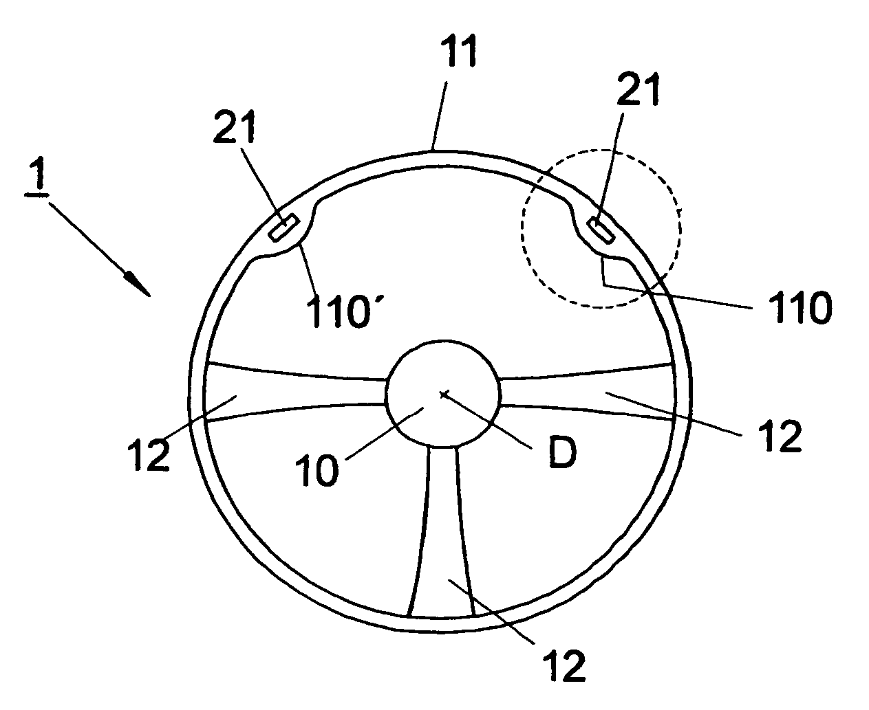
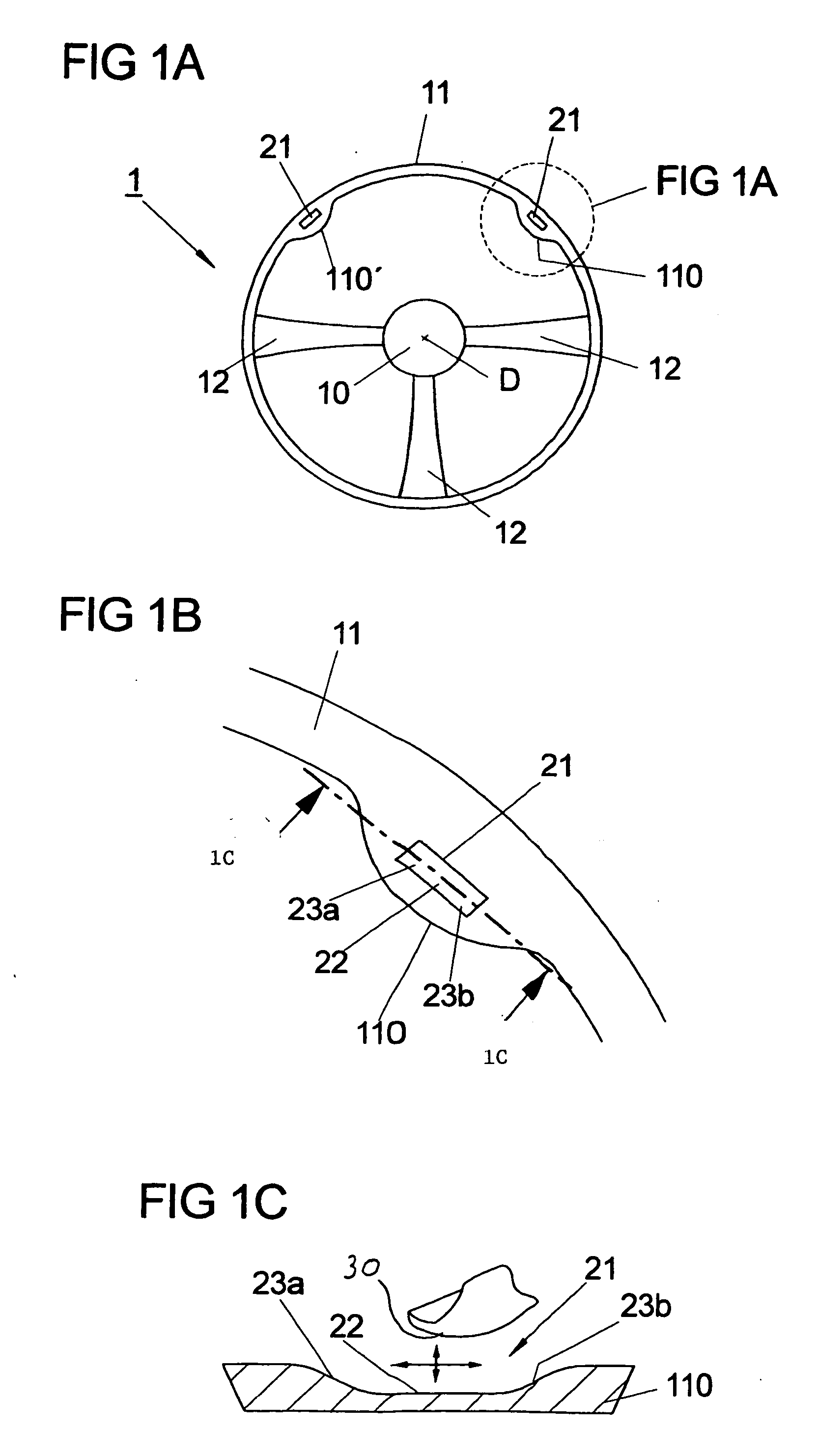
[0035] the steering wheel 1 which is illustrated in FIG. 1A comprises an annular steering wheel rim 11 with an outer contour which is essentially circular. This steering wheel rim 11 is attached, fixed in terms of rotation, to the hub element 10 arranged in the center of the circular outer contour of the steering wheel rim 11 by means of three steering wheel spokes 12 which start from the steering wheel rim 11 and are directed inward.
[0036]FIG. 1A shows the hub element 10 in a circular shape in a plan view. The outer shape of the hub element 10 is influenced, on the one hand, by the fact that it usually accommodates an airbag module. Furthermore, the visual appearance which is expressed in particular in its geometric shape plays an important role for the design in the passenger compartment of the vehicle. Any other geometric embodiment of the hub element 10 which departs from the illustration selected in FIG. 1A is also covered by the invention.
[0037] The same applies to the geomet...
second embodiment
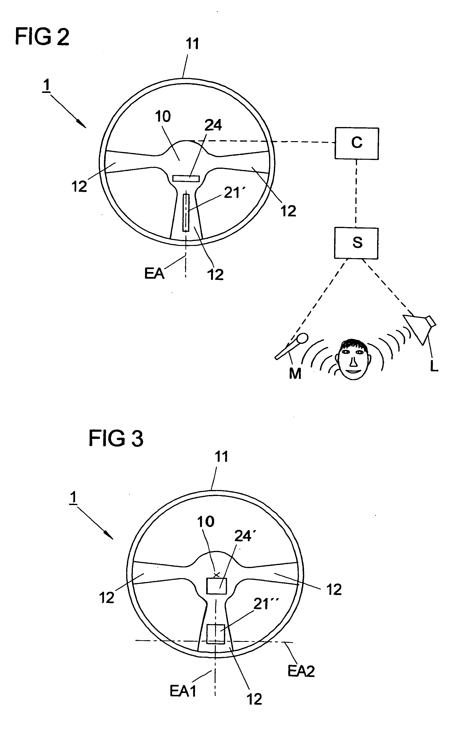
[0047]FIG. 2 shows the steering wheel 1 according to the invention. The basic design of the steering wheel 1 corresponds to that shown in FIG. 1A. The statements made with respect to FIG. 1A therefore apply correspondingly to the matching features. Identical components are provided with identical reference symbols.
[0048] In contrast to the first embodiment of the steering wheel 1, a sensor device with an extended functional face 21′ is not arranged in the region of a bulge on the steering wheel rim 11 but rather on a steering wheel spoke 12. If the steering wheel spoke 12 is one which is grasped by the hands of a driver of a vehicle during customary steering movements owing to the arrangement of said steering wheel spoke 12, the arrangement of the extended functional face 21′ in a depression is not necessary.
[0049] With the steering wheel which is shown in FIG. 2, all that is probable is that a driver of a vehicle grasps the two horizontally arranged steering wheel spokes 12. For t...
third embodiment
[0055]FIG. 3 illustrates the steering wheel 1 according to the invention. The basic design of the steering wheel 1 corresponds to that shown in FIGS. 1A and 2. The preceding statements therefore apply correspondingly to the matching features. Identical components are provided with identical reference symbols.
[0056] In contrast to the first two embodiments of the steering wheel 1, in the third embodiment of the steering wheel 1 a sensor device is provided with a functional face 21″ which extends on the lower steering wheel spoke 12 as an extended functional face 21″ along a first axis EA1 of extent and a second axis EA2 of extent which is arranged perpendicularly with respect to the first axis. The first axis EA1 of extent starts from the axis D of rotation of the steering wheel 1 and runs in the radial direction via the lower steering wheel spoke 12 to the steering wheel rim 11. The second axis EA2 of extent runs perpendicularly with respect to the first axis EA1 of extent, essentia...
PUM
 Abstract
Description
Claims
Application Information
 - R&D
- Intellectual Property
- Life Sciences
- Materials
- Tech Scout
- Unparalleled Data Quality
- Higher Quality Content
- 60% Fewer Hallucinations
Browse by: Latest US Patents, China's latest patents, Technical Efficacy Thesaurus, Application Domain, Technology Topic, Popular Technical Reports.
© 2025 PatSnap. All rights reserved.Legal|Privacy policy|Modern Slavery Act Transparency Statement|Sitemap|About US| Contact US: help@patsnap.com


