Magnetic catheter ablation device and method

a magnetic catheter and ablation device technology, applied in the field of magnetic catheter ablation device and method, can solve the problems of difficult positioning of difficulty in precisely locating aberrant tissue, and difficulty in locating catheter and associated electrode or probe, etc., to facilitate the positioning of the second body, increase the magnetic attraction, and facilitate the alignment of the body

Inactive Publication Date: 2005-08-25
ATRICURE
View PDF99 Cites 1313 Cited by
  • Summary
  • Abstract
  • Description
  • Claims
  • Application Information

AI Technical Summary

Benefits of technology

[0031] The method may further be performed using at least one expandible member which is preferably but not exclusively a balloon. A first expandible member is located on one of the first and second bodies, preferably the first body which is introduced to an epicardial surface. The first expandible member is preferably located on the distal end in the vicinity of the source of magnetic force. Expansion of the expandible member moves the source of magnetic force away from the epicardial surface and decreases the magnet force acting on the second or endocardially-disposed body to facilitate positioning of the second body. The expandible member is retracted prior to ablation to increase the magnetic attraction and facilitate alignment of the bodies on the opposite sides of the tissue. The expandible member may be re-inflated to decrease the magnetic force to allow for re-positioning of the second body and / or engagement with other selected ablation locations. A second expandible member may be employed on the first body, preferably in opposed relation to the first expandible member, and may be inflated upon deflation of the first expandible member, so as to bias the epicardially-disposed body adjacent the epicardial surface.

Problems solved by technology

Common problems encountered in this procedure are difficulty in precisely locating the aberrant tissue, and complications related to the ablation of the tissue.
Locating the area of tissue causing the arrhythmia often involves several hours of electrically “mapping” the inner surface of the heart using a variety of mapping catheters, and once the aberrant tissue is located, it is often difficult to position the catheter and the associated electrode or probe so that it is in contact with the desired tissue.
The application of either RF energy or ultra-low temperature freezing to the inside of the heart chamber also carries several risks and difficulties.
It is very difficult to determine how much of the catheter electrode or cryogenic probe surface is in contact with the tissue since catheter electrodes and probes are cylindrical and the heart tissue cannot be visualized clearly with existing fluoroscopic technology.
Further, because of the cylindrical shape, some of the exposed electrode or probe area will almost always be in contact with blood circulating in the heart, giving rise to a risk of clot formation.
Clot formation is almost always associated with RF energy or cryogenic delivery inside the heart because it is difficult to prevent the blood from being exposed to the electrode or probe surface.
Some of the RF current flows through the blood between the electrode and the heart tissue and this blood is coagulated, or frozen when a cryogenic probe is used, possibly resulting in clot formation.
When RF energy is applied, the temperature of the electrode is typically monitored so as to not exceed a preset level, but temperatures necessary to achieve tissue ablation almost always result in blood coagulum forming on the electrode.
Overheating or overcooling of tissue is also a major complication, because the temperature monitoring only gives the temperature of the electrode or probe, which is, respectively, being cooled or warmed on the outside by blood flow.
The actual temperature of the tissue being ablated by the electrode or probe is usually considerably higher or lower than the electrode or probe temperature, and this can result in overheating, or even charring, of the tissue in the case of an RF electrode, or freezing of too much tissue by a cryogenic probe.
Overheated or charred tissue can act as a locus for thrombus and clot formation, and over freezing can destroy more tissue than necessary.
It is also very difficult to achieve ablation of tissue deep within the heart wall.
As the depth of penetration increases, the time, power, and temperature requirements increase, thus increasing the risk of thrombus formation.
Multielectrode catheters have been developed which can be left in place, but continuity can still be difficult to achieve because of the difficulty in maintaining good tissue contact, and the lesions created can be quite wide.
Because of the risks of char and thrombus formation, RF energy, or any form of endocardial ablation, is rarely used on the left side of the heart, where a clot could cause a serious problem (e.g., stroke).
Because of the physiology of the heart, it is also difficult to access certain areas of the left atrium via an endocardial, catheter-based approach.
However, it is still difficult to create long, continuous lesions, and it is difficult to achieve good depth of penetration without creating a large area of ablated tissue.
When used from an endocardial approach, the limitations of all energy-based ablation technologies to date are the difficulty in achieving continuous transmural lesions, and minimizing unnecessary damage to endocardial tissue.
However, this technology creates rather wide (greater than 5 mm) lesions which could lead to stenosis (narrowing) of the pulmonary veins.
Additionally, there is no feedback to determine when full transmural ablation has been achieved.
Consequently, there is no energy delivered at the backplate / tissue interface intended to ablate tissue.
It is important to note that all endocardial ablation devices that attempt to ablate tissue through the full thickness of the cardiac wall have a risk associated with damaging structures within or on the outer surface of the cardiac wall.
As an example, if a catheter is delivering energy from the inside of the atrium to the outside, and a coronary artery, the esophagus, or other critical structure is in contact with the atrial wall, the structure can be damaged by the transfer of energy from within the heart to the structure.
The coronary arteries, esophagus, aorta, pulmonary veins, and pulmonary artery are all structures that are in contact with the outer wall of the atrium, and could be damaged by energy transmitted through the atrial wall.

Method used


Image

  • Magnetic catheter ablation device and method
  • Magnetic catheter ablation device and method
  • Magnetic catheter ablation device and method

Examples


first embodiment

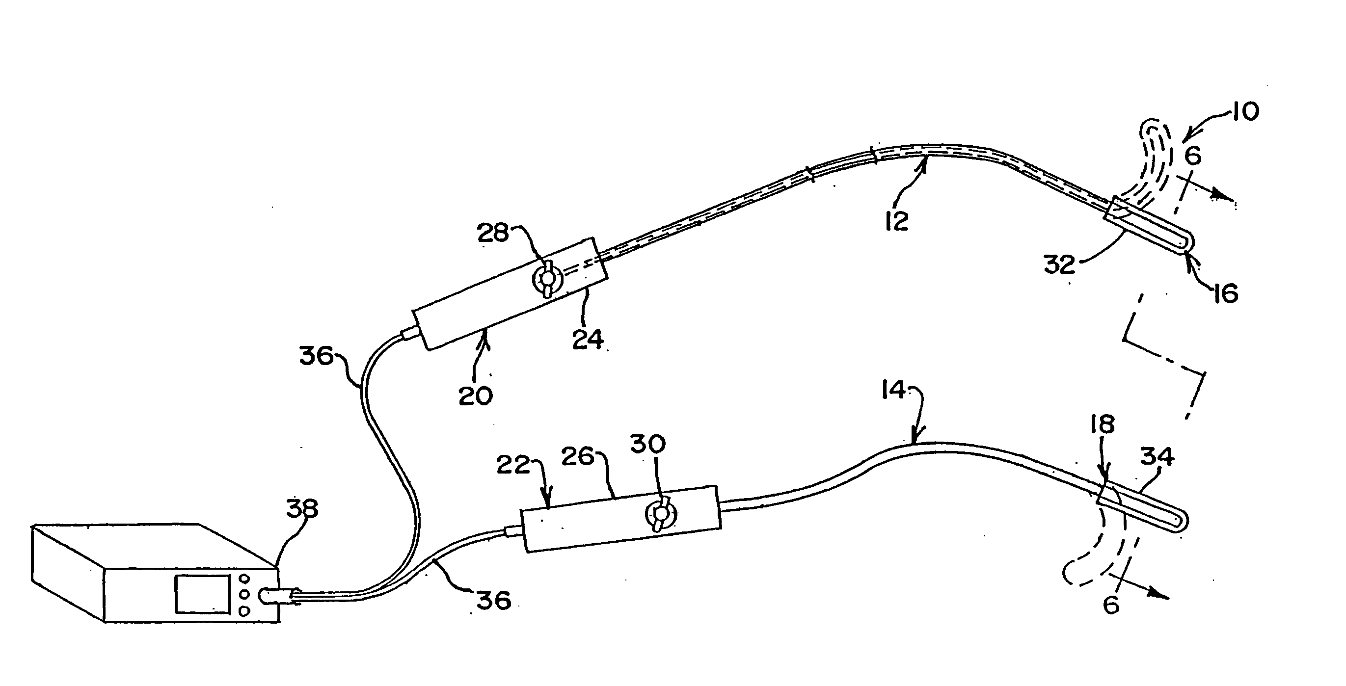
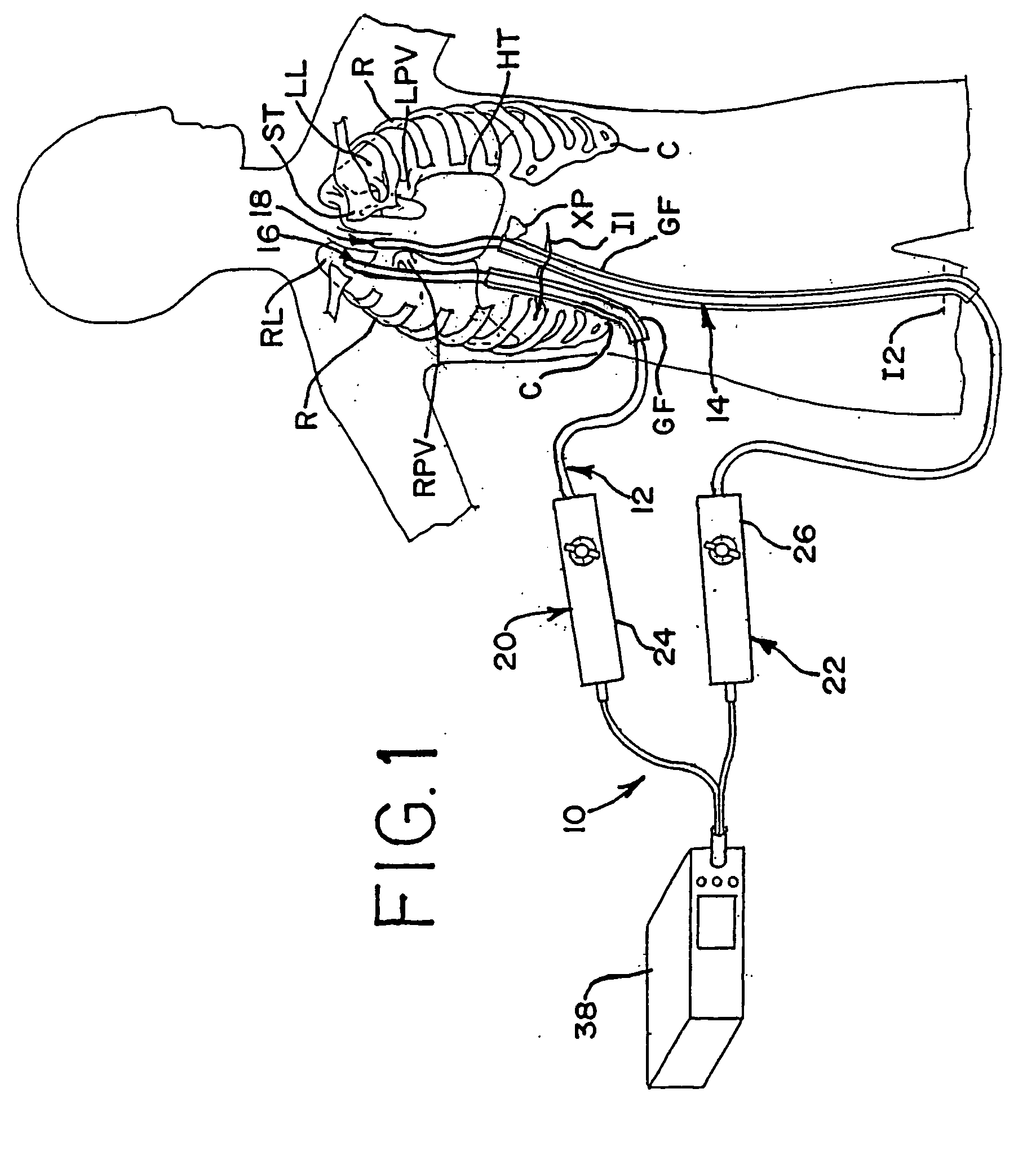
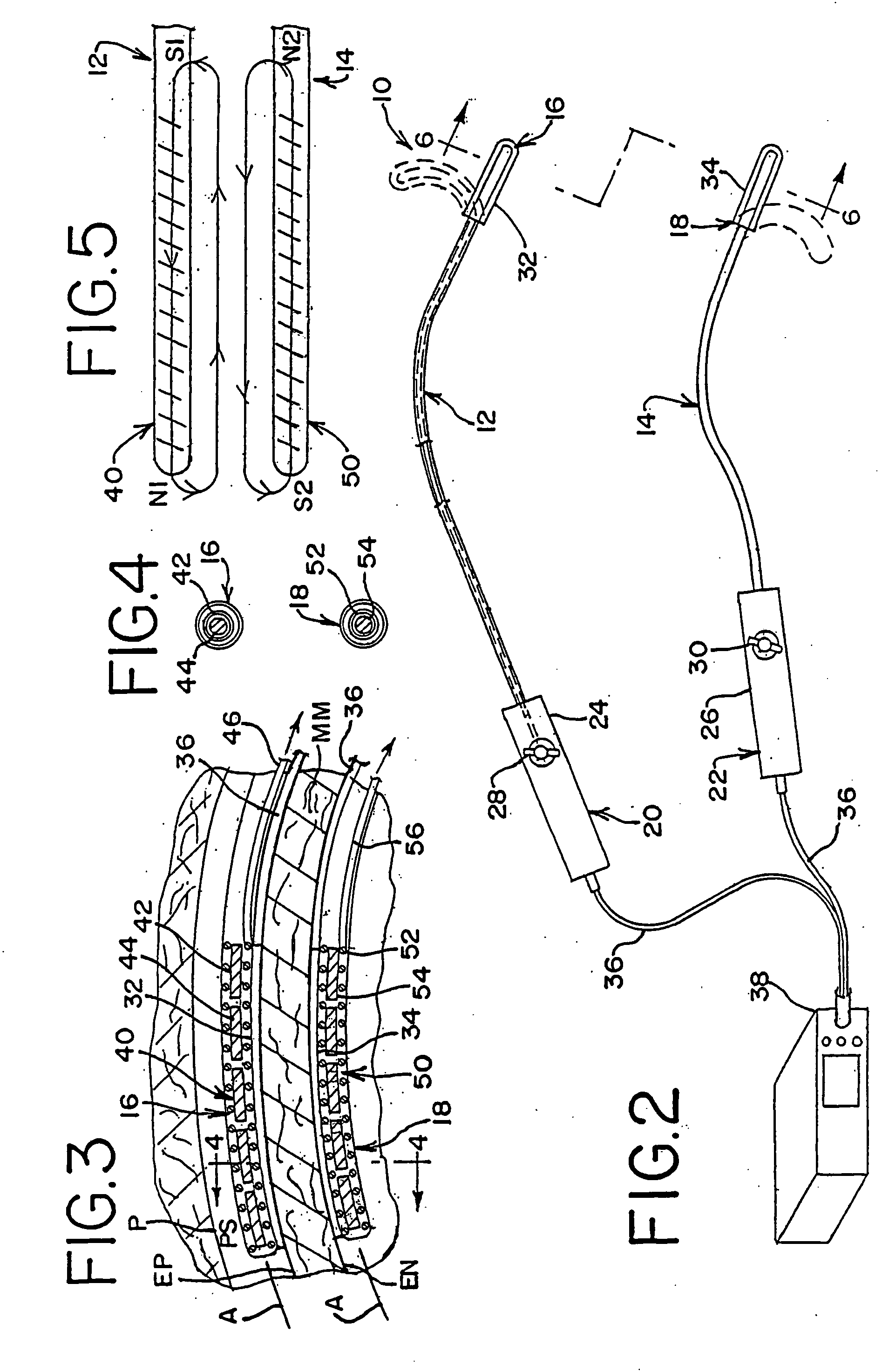
[0084] In accordance with a more specific aspect of the invention, FIGS. 3-5 illustrate various views of the distal ends 16 and 18 of the apparatus. In FIG. 3, first and second bodies 12 and 14 have an exterior surface which defines an interior cavity and each body defines a corresponding axis A along its length. The shape and orientation of the bodies may vary apart from that shown in the views. By way of example and not limitation, the transverse shape of the bodies, which is shown in FIG. 4 as circular, may also be oblong or elliptical, as shown in FIGS. 8 and 20, square or rectangular, as shown in FIG. 6, arcuate, or other geometries, such as the examples shown, not by way of limitation, in FIGS. 12, 14, 23-24 and 26-28 which utilize planar, concave or convex contours, or a combination thereof on the surface or surfaces of the apparatus which contact the layer tissue. Other shapes or geometries are also possible.

[0085] In FIG. 3, the distal end 16 of the first body 12 further in...

third embodiment

[0103]FIGS. 7 and 8 show the apparatus 120. Each of the first and second bodies, respectively indicated at 122 and 124, have sources of magnetic force and magnetically attractive elements, generally indicated by respective reference numbers 126 and 128 and, in this embodiment, are each comprised of electromagnets which have lines of magnetic force, as shown in FIG. 10, upon activation by the current source.

[0104] The embodiment of FIGS. 7 and 8 is similar to the first embodiment of FIGS. 3-5 except that the coil wires of each electromagnet are disposed along an axis which is transverse to the axis A of each distal end, respectively indicated at 130 and 132. The electromagnets in each distal end 130 and 132 are spaced relative to each other along the body axis. Ablation members 134 are also spaced from one another along each distal end and are generally, but not exclusively, aligned with respective electromagnets. The ablation members 134 are positioned in the upper and lower surface...

fourth embodiment

[0107] Turning now to FIGS. 11-12, the apparatus generally indicated at 140 is shown having first and second bodies, respectively 142 and 144 (FIG. 12) with corresponding distal ends 146 and 148. A respective source of magnetic force 150 and a magnetically attractive element 152 are each in the form of at least one electromagnet. Each electromagnet is disposed in a yet further orientation than those previously described above. Each of the distal ends of the first and second bodies are identical to one another and, as such, only one will be described.

[0108] At least at the distal end 148 of the second body 144 the body has a transverse shape which includes a planar surface facing the tissue layer and a convex surface facing away from the tissue layer. Relative to the axial direction of the body shown in FIG. 11, the electromagnets 152 are oriented in several spaced rows carried by the distal end. As shown in FIG. 12, each row has a coil wire which is curved approximately 180 degrees ...


PUM


Abstract

A method and apparatus for ablation of a layer of tissue is achieved by providing first and second bodies on opposed sides of the tissue. The first body includes a first ablation member and a source of magnetic force adjacent one side of the tissue. The second body includes a second ablation member and a magnetically attractive element responsive to the magnetic force adjacent the other side of the tissue. The magnetic attraction between the source and the attractive element is adapted to align the first and second bodies in opposed relationship on the opposed sides of the tissue. One of the first and second bodies may include at least one expandible member for controlling the magnetic attraction between the bodies.

Description

BACKGROUND OF THE INVENTION [0001] This application is a non-provisional application which claims the benefit of provisional application Ser. No. 60 / 546,138, filed Feb. 20, 2004, which application is incorporated by reference herein. [0002] Atrial fibrillation is the most common heart arrhythmia in the world, affecting over 2.5 million people in the United States alone. Ablation of cardiac tissue, in order to create scar tissue that poses an interruption in the path of the errant electrical impulses in the heart tissue, is a commonly performed procedure to treat cardiac arrhythmias. Such ablation may range from the ablation of a small area of heart tissue to a series of ablations forming a strategic placement of incisions in both atria to stop the conduction and formation of errant impulses. [0003] Ablation has been achieved or suggested using a variety of techniques, such as freezing via cryogenic probe, heating via RF energy, surgical cutting and other techniques. As used here, “a...

Claims


Application Information

Patent Timeline
Patent Type & Authority Applications(United States)
IPC IPC(8): A61B18/14
CPCA61B18/14
Inventor HOOVEN, MICHAEL D.RISTER, DAVID W.
Owner ATRICURE
Why Eureka
Try Eureka