Stackable tray

a technology of trays and trays, applied in the field of trays, can solve the problems of damage to products, inability to address the crosswise nesting of trays, and space required to store or transport the largest possible quantity of articles or products without damag

Inactive Publication Date: 2005-08-25
PROARCE DE C V
View PDF16 Cites 43 Cited by
  • Summary
  • Abstract
  • Description
  • Claims
  • Application Information

AI Technical Summary

Benefits of technology

[0009] The present invention is intended to solve the above-mentioned problems. Thus, one goal of the invention is to provide a receptacle or container, specifically, a stackable or nestable tray, for the storage or transport of the tray itself or of products to be stored or transported on the tray, that has a long useful lifetime even under harsh working or handling conditions, which is achieved through a combination of structural elements, such as a sliding guide or groove, corners, male-female sockets, and chamfered corners, which combination avoids the concentration of stresses under a normal load or overload. In order to achieve this combination, consideration was given to the working conditions to which the trays would be subjected, such as dragging force, overload, the type of transport to be utilized, and the roads over which the trays would be transported, as well as careful or careless handling by various operators, including operators who may have a disability or handicap.
[0010] Another goal of the invention is to provide a receptacle or container or tray with handholds that are ergonomically (anatomically) designed, in order to provide greater comfort and safety for the operator, so that the product located on the tray receives better treatment during the handling of the tray. The design of these handholds includes a series of protective strips or ridges, which make the handholds more resistant to damage caused by dragging, thereby considerably increasing the useful lifetime of the trays.
[0011] Another goal of the present invention is to provide trays with differentiated handholds that allow the operator to identify, rapidly and easily, the proper side for stacking, stowing, or nesting the trays, as desired, including doing so simply by touch.
[0012] Yet another goal of the present invention is to provide the trays with a dual guide or groove in the base of the feet, similar to a so-called “shoe” or skate”, to provide better fitting and securing of the trays, thereby preventing them from becoming separated during rough or sudden movements while they are being stored or transported. The dual guide or groove is located along the length of the sides of the trays, so as to allow the feet to be displaced with greater safety, by preventing the trays from becoming separated or departing from their position during transport or handling, and also by preventing the feet of the tray from exerting a force that would deform the guide or groove, or even break it, because of the weight or overweight of the products that are received, held, transported, or lodged on the trays.
[0014] Yet another goal of the present invention is to provide trays that are narrower (but without their narrowness being a limiting factor), that can be stacked on top of other trays that are wider, and that can also be combined or interleaved, in order to store products with smaller dimensions or different capacities.

Problems solved by technology

It is known that one of the principal problems that currently exist in warehouses or transport vehicles is that of the space required to store or transport the largest possible quantity of articles or products without damaging them.
It also describes the use of trays of different heights for stacking; however, it does not address the crosswise nesting of trays of different heights.
However, this patent has the disadvantage that when sudden movements occur due to handling by the operator, the upper trays are easily separated from the lower trays, thereby causing damage to the product and rendering it unacceptable to the purchaser.
Moreover, the trays have a very short sliding groove, which does not allow rapid alignment during the sliding operation, and also causes the trays easily to become separated.
The trays include handholds that can injure the operators or that simply are not convenient for the operators in terms of proper handling of the trays, and that are not designed to withstand rough handling by the operators or the conditions that are present in trucks when they encounter potholes, earthfills, winding roads, etc.
The result is that their useful lifetime is reduced significantly, and that the trays become separated while being transported by such trucks, which can cause damage to, and rejection of, the transported products.
The marks that the trays may contain in order to indicate to the operator the angle at which they are stacked tend to disappear rapidly as a result of the daily use and frequent cleaning that the tray must undergo, especially when the tray is used to transport food products that demand minimum levels of hygiene, thereby causing the operator to spend additional time determining whether a tray is stacked or nested.
All of the above-mentioned trays have slots or small openings in the sides in which small amounts of the product can become lodged and can decompose, and sometimes these slots or openings can even lead to substandard cleaning of the tray.
It should be noted that because of its design, it may not be possible for such a tray to be handled by an individual who has a disability or handicap.
The stop elements that are used when the tray is placed in the crosswise position are not sufficient to prevent the tray from departing from its so-called “stable” position, with the result that some products are damaged when they fall off the tray.
Furthermore, this tray does not have a male-female socket which, in the stacked position, allows the upper tray to be affixed securely to the lower tray.
Yet furthermore, the design of this tray does not allow a tray of a different width to be stacked on top of a lower tray, and does not contemplate the combination or alternation of trays of different widths during stacking.
An additional disadvantage of the tray in U.S. Pat. No. 6,394,274 is that it runs the risk that the groove or sliding guide for the feet, as well as the sides and handholds, may become deformed or break within a short period of time, because of rough handling by the operator or even because of the weight of the product plus the weight of each stacked tray.
Another disadvantage of the trays in the prior art is that there is a risk that the trays will be overturned if, for example, an operator accidentally leans against the trays, because there is no balancing support on one side of the trays.

Method used


Image

  • Stackable tray
  • Stackable tray
  • Stackable tray

Examples


Embodiment Construction

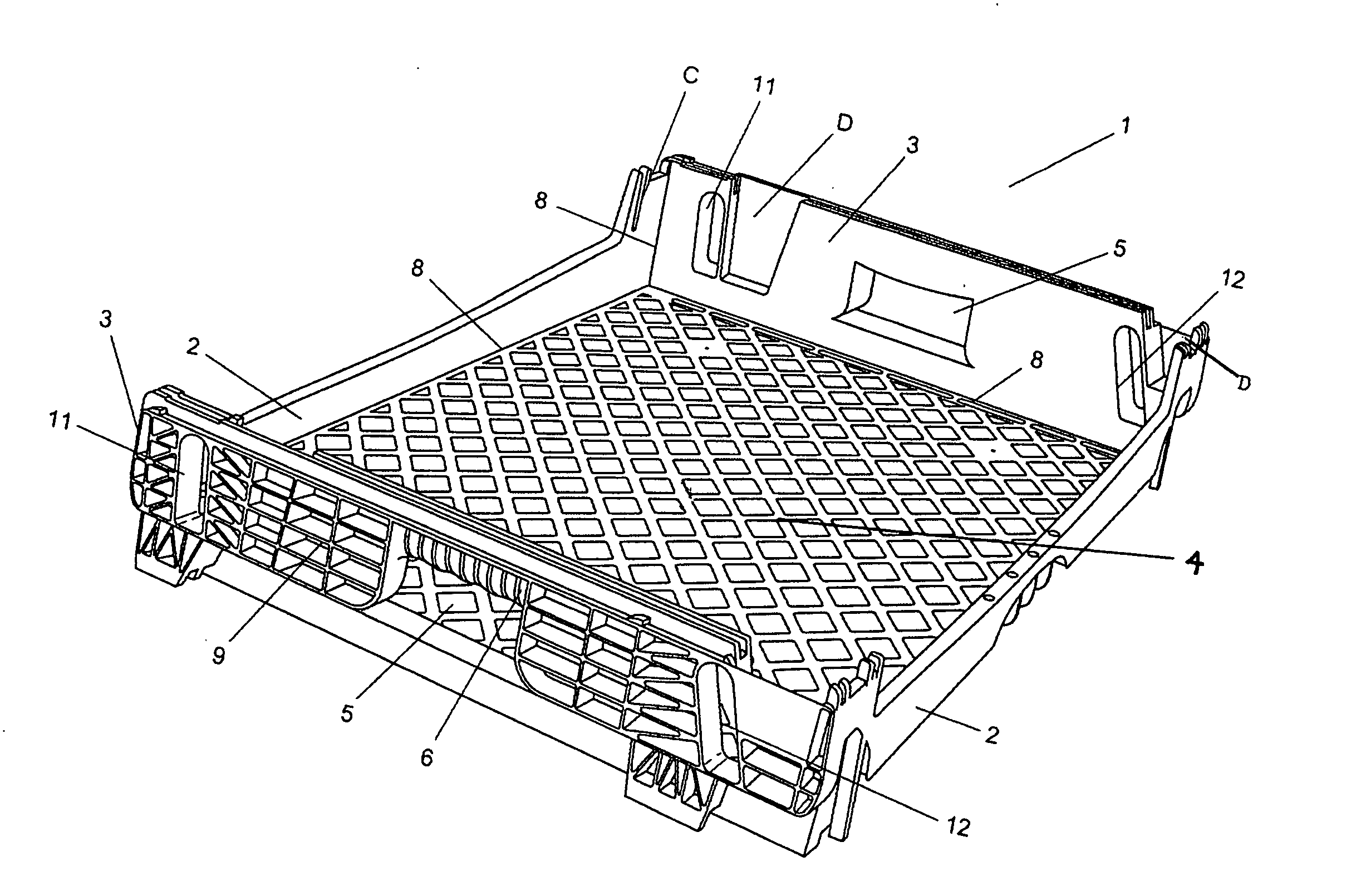
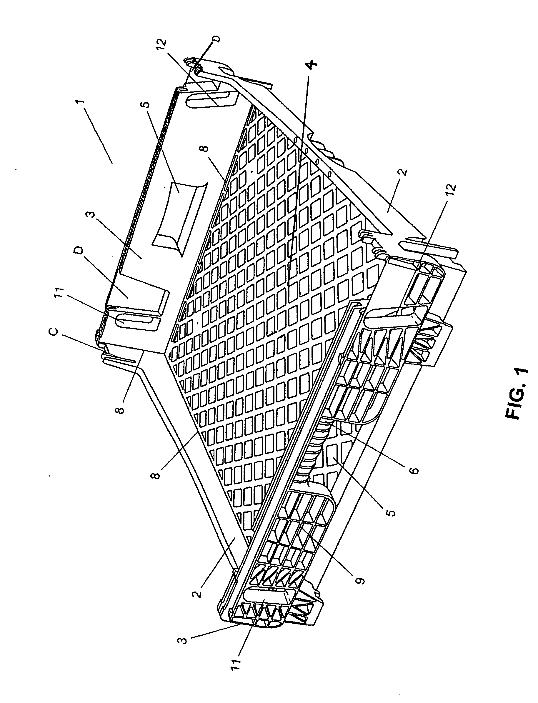
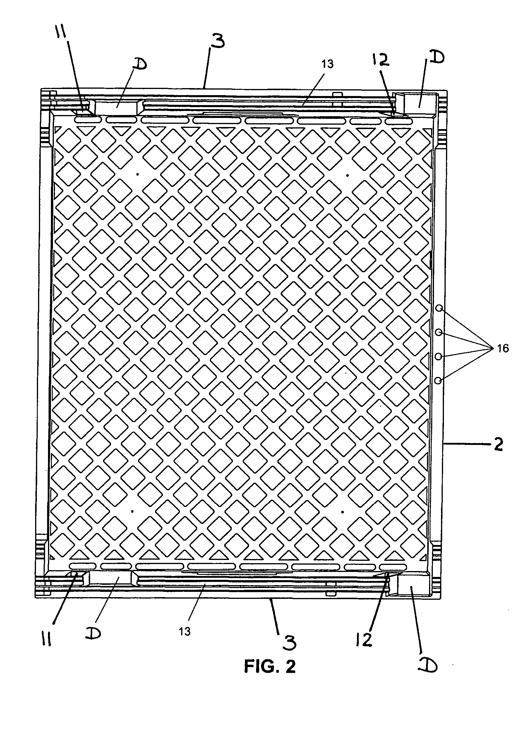
[0032] With reference now to the figures, FIG. 1 shows how the receptacle, container, or tray (1) is designed in a manner similar to a box, including two sides of reduced height (2), which have, on the inside of two of their corners, slots or recesses (C) for receiving or mating with a vertical structural element or rod, and two sides of greater height (3), and a floor element (4) that may have various different design patterns, or no patterns, or which may be perforated or uniformly solid, as desired, although it is preferably perforated, so as to allow ventilation when the products consist, for example, of perishable items, bread, etc. The sides of greater height have sliding elements in order to allow the sliding of an upper tray to be stacked, recesses, and coupling elements (D) (two on each side), in which feet are seated so as to allow an upper tray to be nested or stowed (see FIGS. 8, 9, and 11), thereby providing spaces of different heights, depending on the required orienta...


PUM


Abstract

The present invention relates to containers and, more specifically, to trays that can be arranged at angles over the range from 0 to 180° so that, through this rotation, different height positions can be obtained; that include ergonomic handholds, which allow an operator to identify, by touch, the proper side for stacking or stowing or adding trays, as required; a dual guide on the base of the feet, to prevent the feet from separating when the trays are stowed; a dual track or groove along the sides, to allow so-called “shoe” or “skate” elements to slide and to prevent the trays from departing from their position; socket parts (male-female), to ensure that the upper trays do not become disengaged during sudden movements and to allow the trays to be stacked to different heights; and stops or protuberances in both the upper part and the lower part of the tray, to prevent the upper trays from sliding freely along the groove of the lower tray or along its side, depending on their position.

Description

CROSS-REFERENCE TO RELATED APPLICATIONS [0001] This invention claims the benefit under 35 U.S.C. § 119 of Mexican Application No. PA / a / 2004 / 000921 filed Jan. 28, 2004, which is herein incorporated by reference in its entirety. FIELD OF THE INVENTION [0002] The present invention relates to stackable containers and more specifically to stackable trays for storing or transporting articles or products with different dimensions, which trays may be oriented and safely placed on top of each other in accordance with the dimensions of the product or article to be stored or transported. BACKGROUND OF THE INVENTION [0003] It is known that one of the principal problems that currently exist in warehouses or transport vehicles is that of the space required to store or transport the largest possible quantity of articles or products without damaging them. Accordingly, users have developed, or have asked companies that are experts in the field to design, receptacles or containers that, depending on ...

Claims


Application Information

Patent Timeline
IPC IPC(8): B65D1/34B65D21/00B65D21/04B65D85/62
CPCB65D21/043B65D1/34
Inventor FERNANDEZ, ENRIQUE CHAVEZFORMOSO, JOSE LUIS ALEGRIA
Owner PROARCE DE C V
Why Eureka
Try Eureka