
Directional flow sensor inhaler

a flow sensor and inhaler technology, applied in the field of inhalation devices, can solve the problems of not having the ability to detect the direction of the flow of air through the acoustic sensor, difficult for some users, and difficult for others, so as to improve the usability of children, reduce the need for training, and be more user-friendly

Inactive Publication Date: 2005-08-25
MICRODOSE THERAPEUTX INC
View PDF56 Cites 102 Cited by
  • Summary
  • Abstract
  • Description
  • Claims
  • Application Information

AI Technical Summary

Benefits of technology

[0009] The present invention provides an improvement over the prior art inhalation devices such as our aforementioned U.S. Pat. No. 6,152,130. The present invention provides a directional acoustic flow sensor to operate the inhaler. The direction acoustic flow sensor detects the detection of the airflow into the inhaler and permits the activation of the inhaler when the user inhales and not when the user exhales. A preferred embodiment includes an acoustic controller, wherein the acoustic controller includes an acoustic element to sense air flow around the element and for producing signals representative of a frequency, direction and amplitude of the airflow, the signals being used to control (e.g., activate, deactivate, apply incremental voltage, etc.) certain components of the inhalation device. This feature helps make the inhaler more user friendly, minimizes training necessary to use the device and improves usability for children.
[0010] Preferably, the acoustic element is a microphone element or pressure transducer positioned within the air passage of an inhalation device, (e.g., a dry powder inhaler) that produces signals in response to the inhalation air flow. These signals are used to control certain components of the inhaler, e.g., a high frequency vibrator, an electrostatic plate, timer, counter, etc. Also preferably, these signals are used to activate / control certain components of the inhalation device to maximize the inhalation effectiveness to obtain maximum patient benefit from the medicament.
[0011] Thus, the present invention provides a fully automated inhalation device, which is activated on inhalation only, that permits optimal utilization of the particular medication. For example, acoustic signals can be used to trigger the high frequency vibrator only when the patient has achieved optimum (e.g., maximum) inhalation effort, thereby ensuring that the full (proper) dosage of medicament properly enters the patient's respiratory system. Alternatively, these signals (breath-activated signals) can be used to progressively apply increasing power to, or, sequentially activate / deactivate the various components of the inhalation device to achieve optimal inhalation dosage.

Problems solved by technology

This can be difficult and painful for some users (e.g., patients suffering from extreme arthritis).
This can also be difficult for some users (e.g., very young patients, patients suffering from neuromuscular disorders, etc.).
However, this acoustic sensor flow does not have the ability to detect the direction of the flow of air.
Thus, a heretofore unaddressed need exists in the industry to address the aforementioned deficiencies and inadequacies.

Method used


Image

  • Directional flow sensor inhaler
  • Directional flow sensor inhaler
  • Directional flow sensor inhaler

Examples


Embodiment Construction

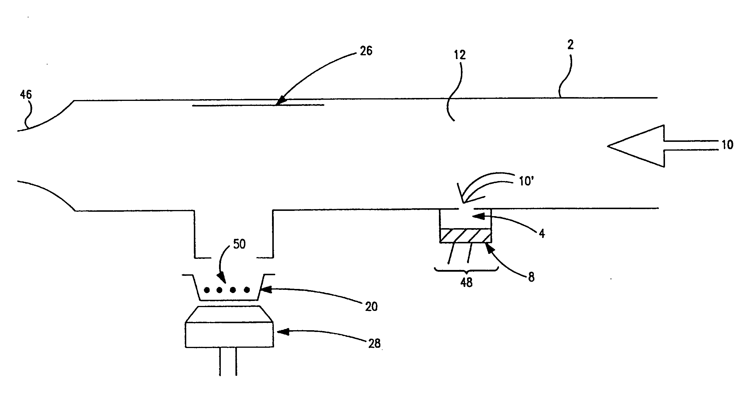
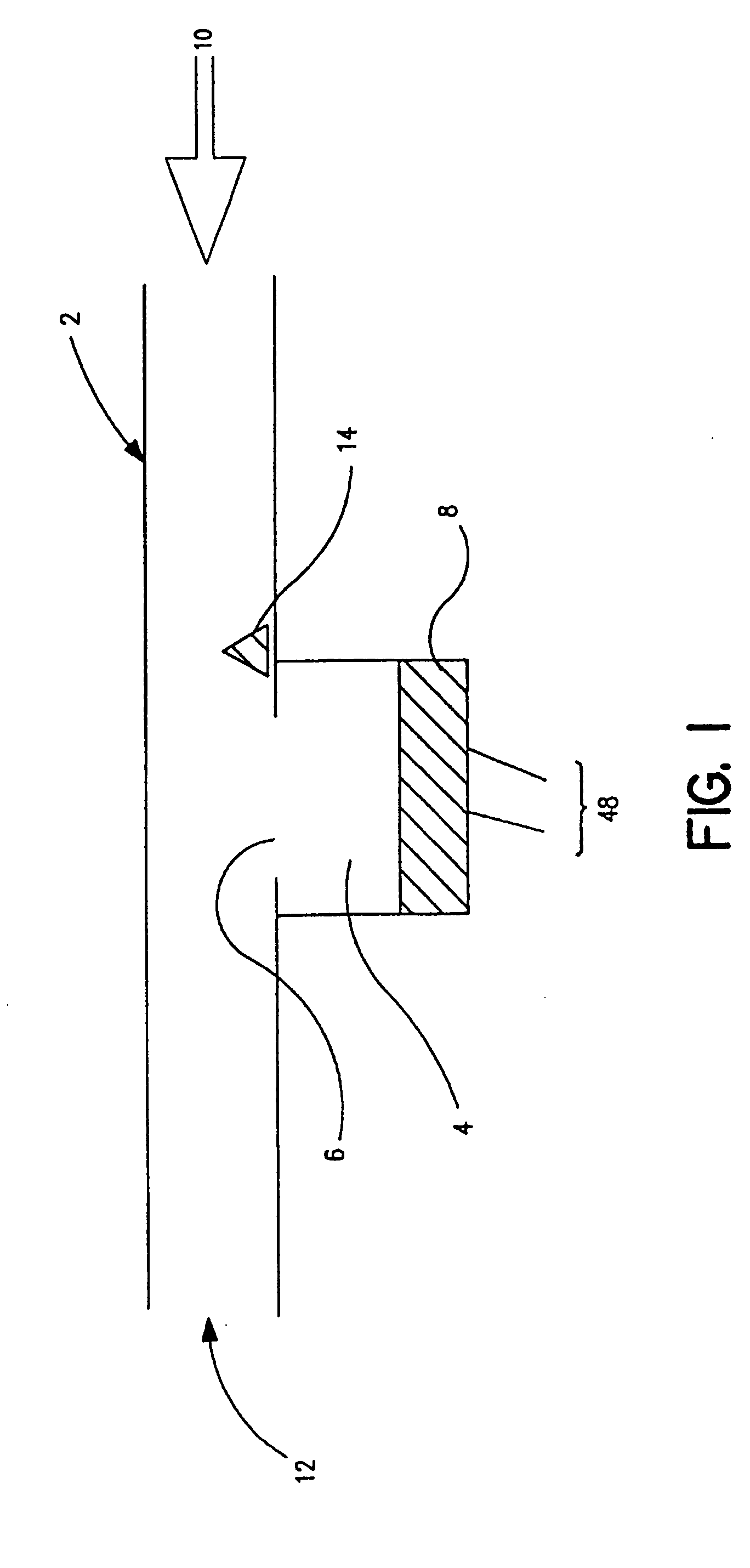
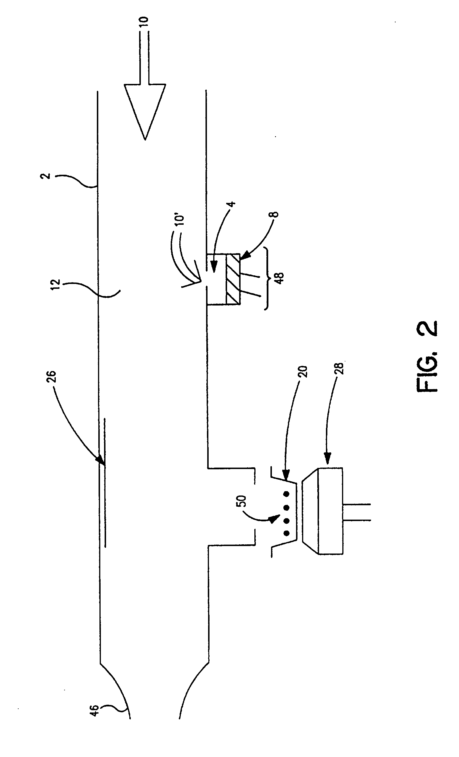
[0019] Referring to FIGS. 1 and 2, a cross-sectional view of an airflow passage 12 of an inhalation device 2 is depicted. It should be noted at the outset that the airflow passage 12 depicted in FIG. 1 is a generalized airflow passage of a typical inhalation device, such as those discussed above. However, the present invention is intended to be adapted to any inhalation device, regardless of the particular geometry of the airflow passage. At its most basic level, the present invention operates by providing an air flow sensor 8 to detect air flow turbulence around the sensor 8 (i.e., inspiratory air flow rate of a user of the inhaler) and to control various components of the inhalation device 2, as a function of the amplitude, direction and / or frequency of the detected airflow turbulence, as described below.

[0020] As shown in FIG. 1, air 10 (or any other fluid) enters the airflow passageway 12, typically by the respiratory activity of a patient inhaling on the device 2. As air 10 fl...


PUM


Abstract

An fluid sensor to activate and control various components of an inhalation device. The fluid sensor includes an acoustic element, such as a microphone, positioned within said inhalation device to detect fluid within the device and output signals representative of the frequency, direction and / or amplitude of the fluid. These signals control and activate an electrostatic plate and / or a high frequency vibrator.

Description

CROSS REFERENCE TO RELATED APPLICATION [0001] This application claims priority to co-pending U.S. Provisional Application entitled “Directional Flow Sensor Inhaler”, having Ser. No. 60 / 547,324, Filed Feb. 24, 2004 which is entirely incorporated herein by reference.TECHNICAL FIELD [0002] The present invention relates generally to the field of inhalation devices, and more specifically, to inhalation devices that utilize acoustic control to facilitate breath activation of different systems of the inhalation device. Particular utility for the present invention is found in the area of facilitating inhalation of powdered medications. BACKGROUND OF THE INVENTION [0003] Certain diseases of the respiratory tract are known to respond to treatment by the direct application of therapeutic agents. As these agents are most readily available in dry powdered form, their application is most conveniently accomplished by inhaling the powdered material through the nose or mouth. Alternatively, the drug...

Claims


Application Information

Patent Timeline
Patent Type & Authority Applications(United States)
IPC IPC(8): A61M15/00A61M15/02A61M16/00
CPCA61M15/0085A61M15/02A61M15/0091A61M2202/064A61M2205/3375A61M2016/0021A61M15/008A61M15/0083A61M11/005A61M15/001A61M2205/3334
Inventor GUMASTE, ANAND V.BOWERS, JOHN
Owner MICRODOSE THERAPEUTX INC
Learn More