
Adaptive MIMO architecture

a technology of mimo and transmission scheme, applied in the field of multiantenna transmission scheme for wireless communication network, can solve the problems of limited peak rate improvement, increased complexity of transmitter and receiver, and limited information concerning the communication channel being fed back from the receiver

Active Publication Date: 2005-08-18
TELEFON AB LM ERICSSON (PUBL)
View PDF31 Cites 163 Cited by
  • Summary
  • Abstract
  • Description
  • Claims
  • Application Information

AI Technical Summary

Benefits of technology

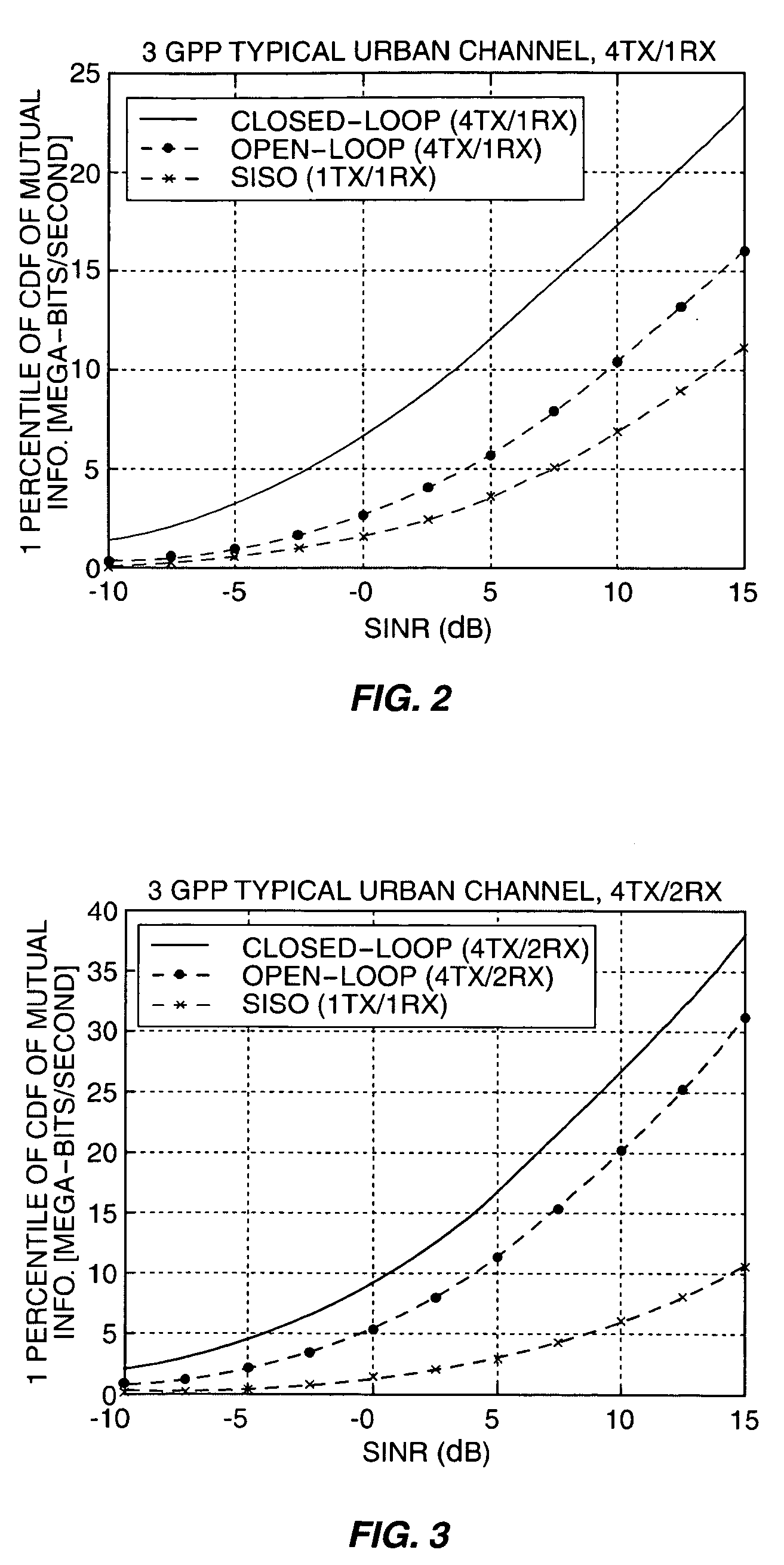
[0006] The present invention relates to an adaptive transmission scheme having at least two levels of adaptation. At the first level, the feedback mode is selected based on some quality metric that indicates receiver performance. For example, the metric may be one or more SINRs at the output of the terminal receiver or the supportable data rate by the receiver. This quality metric may depend on a number of measurable quantities, including the number of the receive antennas, channel quality, mobile speed, the condition of the propagation channel, and/or the available bandwidth between the mobile station and base station. The terminal can calculate this quality metric for closed-loop and open-loop modes and switch to the mode with satisfies the switch criterion. In one exemplary embodiment, the feedback modes include limited feedback or open loop mode and rich feedback or closed loop mode. Transmitter configurations for limited feedback mode include a per antenna rate control (PARC) and spatial multiplexing (SM) combined with code reuse. In these approaches, a data stream is ...

Problems solved by technology

While transmit diversity schemes realize improvements in the SINR, peak rate improvement is limited to single-antenna modulation and coding options.
The trade-off results in greater complexity of the transmitter and receiver.
In limited feedback MIMO systems, only limited information concerning the communication channel is fed back from the receiver to the transmitter.
Unfortunately, there is no one system configuration that performs consistently better than the others over the range of possible operating conditions envisioned for deployment.

Method used


Image

  • Adaptive MIMO architecture
  • Adaptive MIMO architecture
  • Adaptive MIMO architecture

Examples


Embodiment Construction

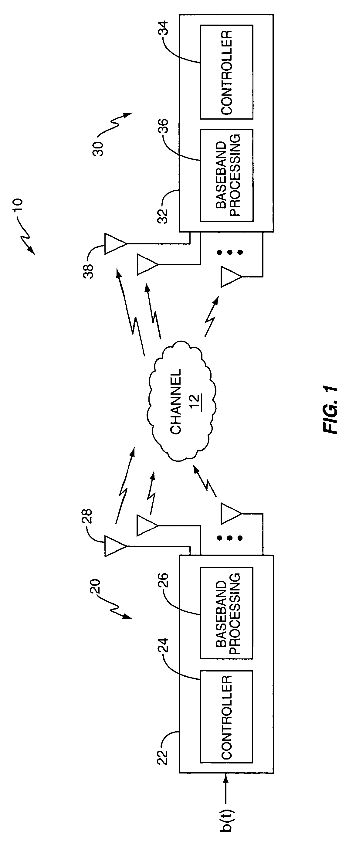
[0013]FIG. 1 illustrates a multiple input / multiple output (MIMO) wireless communication system 10 including a first station 20 and a second station 30. The first station 20 includes a transmitter 22 for transmitting signals to the second station 30, while the second station includes a receiver 32 for receiving signals transmitted by the first station 20. Those skilled in the art will appreciate that the first station 20 and second station 30 may each include both a transmitter 22 and receiver 32 as shown in FIG. 1 for bi-directional communications. In one exemplary embodiment, the first station 20 is a base station in a wireless communication network, and the second station 30 is mobile station.

[0014] An information signal in the form of a binary data stream is input to the transmitter 22 at the first station 20. The transmitter includes a controller 24, a transmit signal processing circuit 26, and a plurality of transmit antennas 28. The controller 24 controls operation of the tra...


PUM


Abstract

An adaptive transmission scheme provides multiple levels of adaptation. At a first level, a selection is made between a limited feedback or open loop scheme and a rich feedback or closed loop scheme. At a second level of adaptation, a diversity mode is selected. Additional levels of adaptation could be employed.

Description

[0001] This application claims priority under 35 U.S.C. §119 to Swedish application no. 04003703 which was filed on 13 Feb. 2004, and which is incorporated herein by reference. BACKGROUND OF THE INVENTION [0002] The present invention relates to multi-antenna transmission schemes for wireless communication networks and more particularly, to an arrangement and a method for adapting between transmitter and receiver configurations responsive to channel conditions and other factors. [0003] In most conventional second generation (2G) and third generation (3G) wireless communication systems, both the transmitter and receiver are equipped with a single antenna. Such systems are known as single input, single output (SISO) systems. In recent years, researchers have proposed using multiple antennas at the transmitter and / or receiver to improve performance of the communication system. Transmit diversity is one example of a multiple antenna transmission scheme that has been proposed as a way of ...

Claims


Application Information

Patent Timeline
IPC IPC(8): H04B1/707H04B7/06H04J13/00H04J99/00H04L1/00H04L1/06H04W16/28H04W28/00
CPCH04B7/061H04B7/0626H04B7/065H04B7/0686H04B7/0689H04L1/06H04B2201/709727H04L1/0002H04L1/0025H04L1/0026H04L1/003H04B7/0691H04B7/0417H04B7/0634
Inventor KRASNY, LEONIDMOLNAR, KARLCHENG, JUNG-FU THOMASGRANT, STEPHENWANG, YI-PIN ERIC
Owner TELEFON AB LM ERICSSON (PUBL)
Learn More