Spacecraft propulsion system

Inactive Publication Date: 2005-08-18
WILSON THOMAS R
View PDF0 Cites 19 Cited by
  • Summary
  • Abstract
  • Description
  • Claims
  • Application Information

AI Technical Summary

Problems solved by technology

Rockets and ion engines are limited in the overall velocity they can impart to the spacecraft by the mass of the vessel and by the size of the spacecraft's fuel supply.
However, solar sails cannot tack and therefore may only be used for propulsion in one direction, that is away from the sun.

Method used


Image

  • Spacecraft propulsion system
  • Spacecraft propulsion system
  • Spacecraft propulsion system

Examples


Embodiment Construction

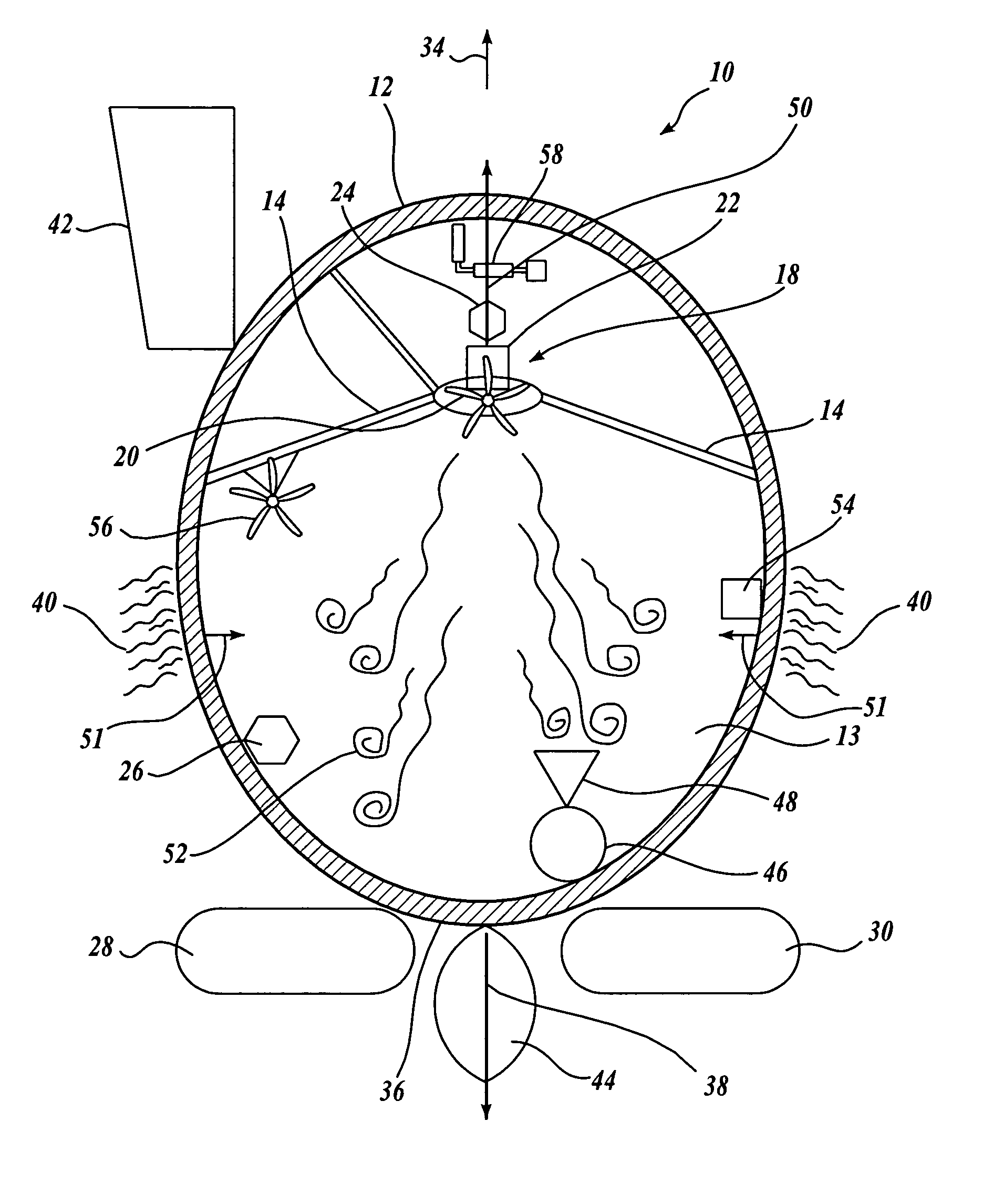
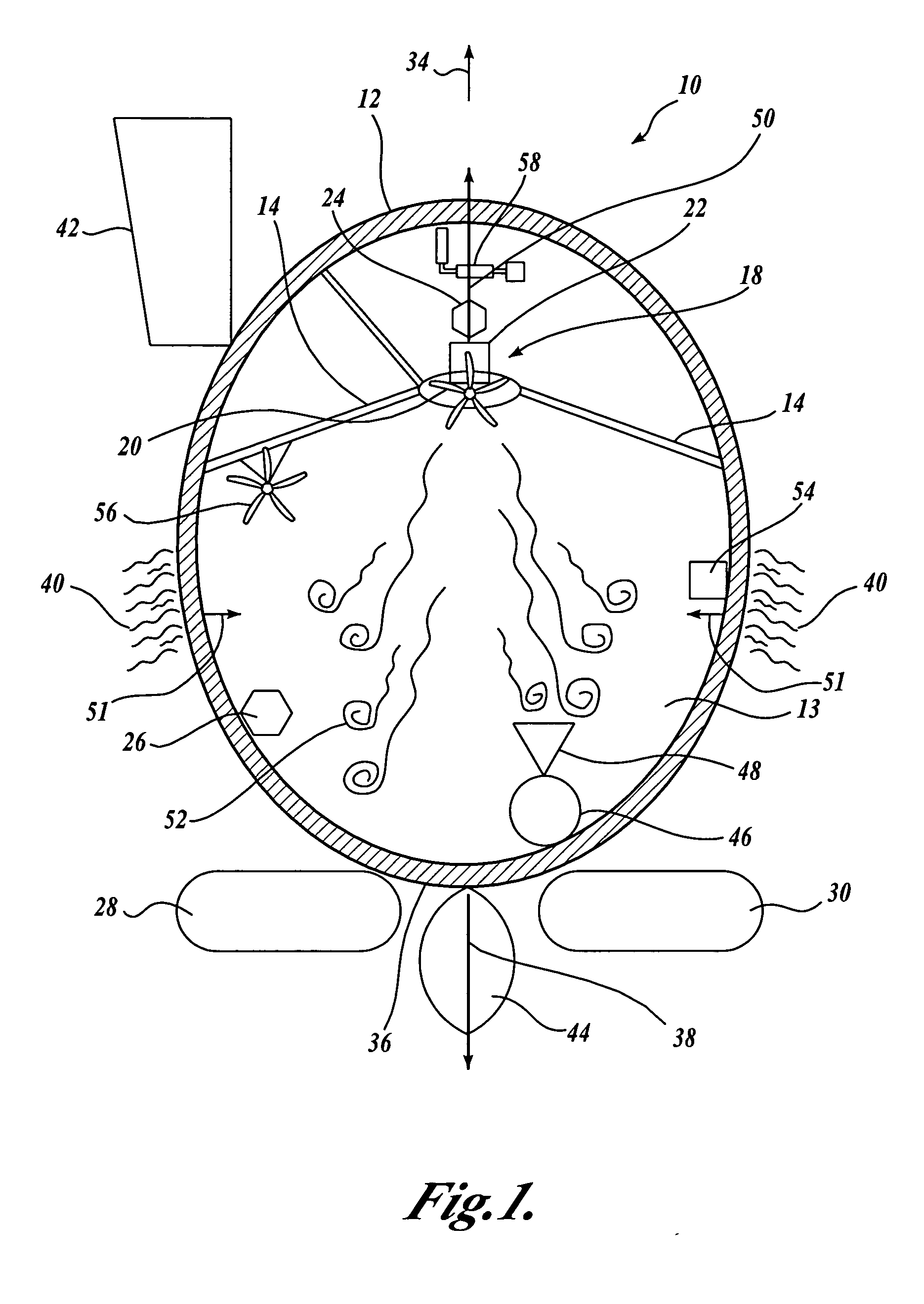
[0012] Referring to FIGS. 1 and 2, one embodiment of a spacecraft 10 formed in accordance with the present invention is depicted. The spacecraft includes a hull 12, which is preferably a pressure hull able to withstand a pressure differential between the outer surface and inner surface of the hull 12. The hull 12 of the illustrated embodiment is preferably spherical or egg shaped and constructed to withstand an atmospheric pressure differential of about one atmosphere between the pressure of the surrounding ambient atmosphere and the pressure within the hull. The hull 12 is designed to contain a fluid 13, one suitable example being air. The pressure hull may be built-up of layers of fabric, composites, foam and structural elements sufficient to contain the pressure gradient across the hull's wall.

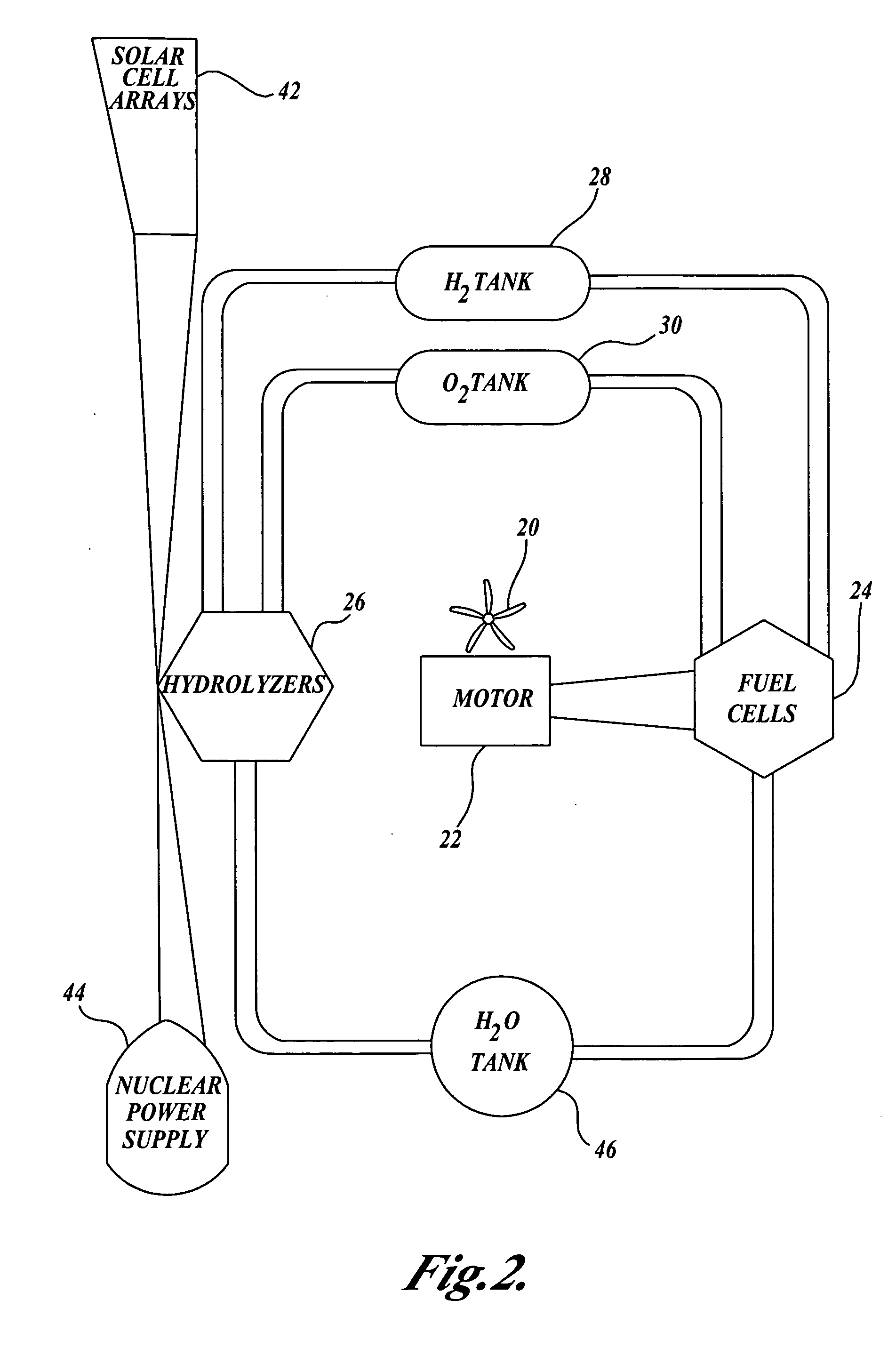
[0013] The spacecraft 10 includes a propulsion system 18 disposed within and rigidly coupled to the pressure hull 12. Preferably, the propulsion system 18 is of a reaction or jet based pro...


PUM


Abstract

A spacecraft is disclosed. The spacecraft (10) includes a pressure hull (12) for containing a gas (13). The spacecraft further includes a propulsion system (18) coupled to the pressure hull so as to be disposed within the pressure hull, the propulsion system operable to generate a propulsion force for propelling the spacecraft through space.

Description

CROSS-REFERENCE TO RELATED APPLICATION [0001] This application is a continuation-in-part application which claims the benefit under 35 U.S.C. §120 of U.S. patent application Ser. No. 10 / 057,507, filed Jan. 22, 2002, the disclosure of which is hereby expressly incorporated by reference.FIELD OF THE INVENTION [0002] This invention generally relates to spacecrafts, and more specifically to spacecraft propulsion systems for accelerating the spacecraft. BACKGROUND OF THE INVENTION [0003] Spacecraft have been and are currently driven by chemical rockets and ion drive propulsion systems, and there are realistic proposals for solar sails and other untried exotic notions. Rockets and ion engines are limited in the overall velocity they can impart to the spacecraft by the mass of the vessel and by the size of the spacecraft's fuel supply. Once the fuel supply is exhausted, the spacecraft is unable to accelerate, decelerate or alter course except by the planned interaction with large gravitati...

Claims


Application Information

Patent Timeline
IPC IPC(8): B64G1/40F03H99/00
CPCF03H99/00B64G1/409B64G1/411
Inventor WILSON, THOMAS R.
Owner WILSON THOMAS R
Why Eureka
Try Eureka