
Micro-volume blood sampling device

a blood sampling and micro-volume technology, applied in the field of obtaining a sample of biological fluid, can solve the problems of difficult task of obtaining a small fluid sample from an individual, for example 100 microliters (l) or less, and achieve the effect of minimizing the transmission of infection, simple manual discharge, and easy and rapid separation of components

Inactive Publication Date: 2005-08-18
AVANTRA BIOSCI CORP
View PDF31 Cites 113 Cited by
  • Summary
  • Abstract
  • Description
  • Claims
  • Application Information

AI Technical Summary

Benefits of technology

[0004] Applicants have designed a simple tool that is capable of performing the multiple tasks of collecting and manipulating a fluid biological sample within a single device, and then recovering a metered amount of the sample for further analysis, such as in a laboratory test for research or monitoring purposes, a screening test, or a diagnostic assay. The device can be used in conjunction with a fluid sample from any source, animate or inanimate. Preferably, the device is used to collect a fluid sample from an animal, e.g., a mammal, a human, a bird, or a reptile. The device further has the advantage of protecting the user from direct contact with the fluid sample, thereby minimizing transmission of infection, e.g., HIV or hepatitis C. In one embodiment, the device is used to draw a predetermined volume of blood from an animal, dilute it in a predetermined ratio, easily and rapidly separate components from the sample by centrifugal force, and permit a simple manual discharge of some or the entire sample in a measured manner. Optionally, the sample collection tool is further enhanced with features useful for identifying and tracking the specimens held and processed within the device, such as tags, bar codes, or surface properties bearing the date, source of specimen, and any other information useful to the handler.
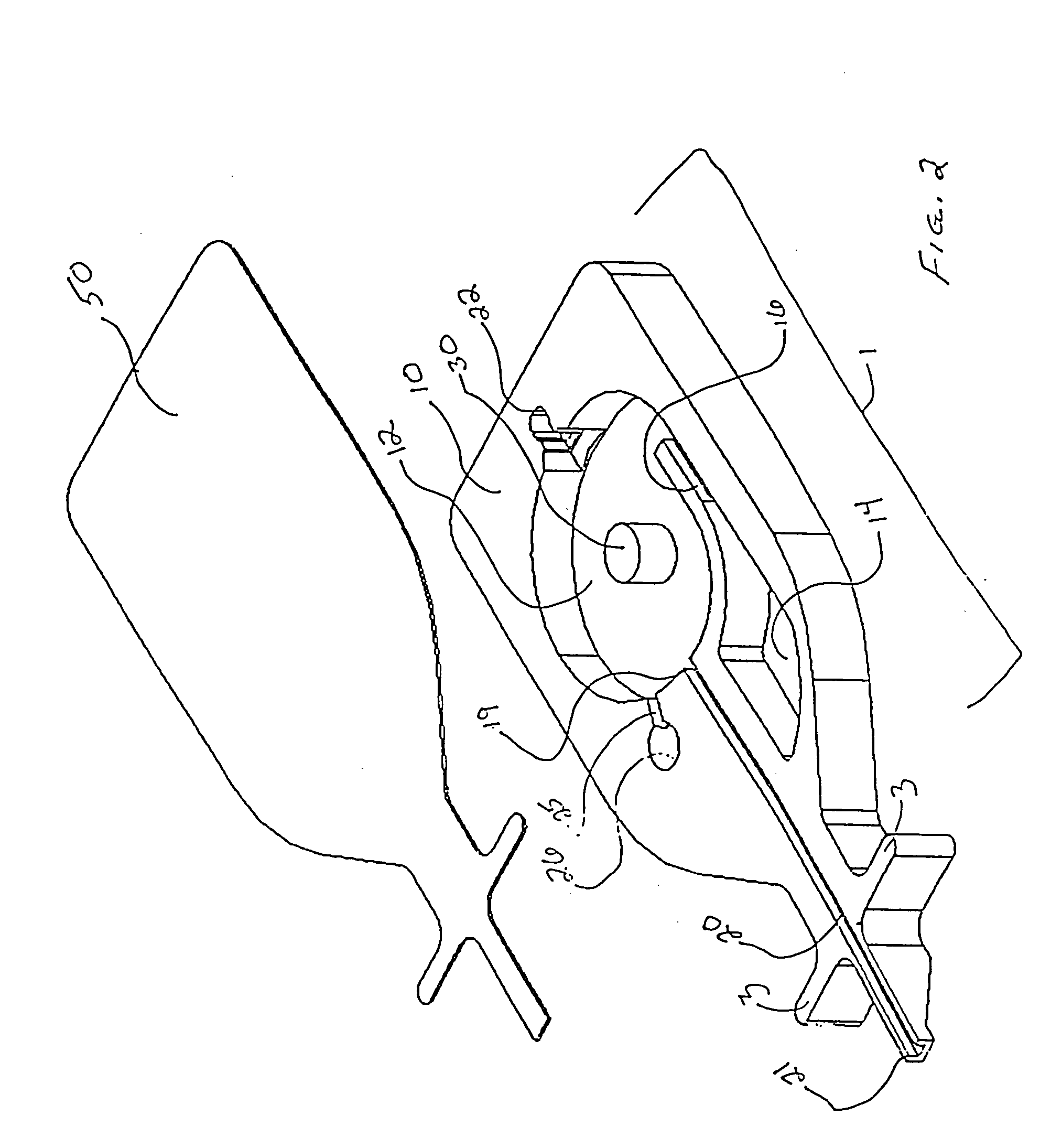
[0006] The processed sample is finally recovered from the device by manual expulsion of the fluid back through the conduit. The device is turned vertically to allow a portion of the liquid in the central chamber to enter into a vent plug, causing the plug to swell and permitting the finger pump to be actuated. A preset volume of fluid is then forced back out of the device through the conduit by pressing and deforming the cover 50 of the receptacle body in a controlled manner. The dimensions of the chamber 12 and the permitted free travel of the cover 50 are pre-chosen so that full pressure on the cover 50 pushes out a metered volume of fluid. Relieving pressure on the cover permits the cover to resume its original position, pulling the fluid in the conduit and air back into the central chamber 12. As the cover 50 is released, the device sucks in the fluid within conduit 20 and air. Only the fluid within the conduit 20 is desired to be retained, so care should be taken to avoid aspiring any fluid back into the device beyond the content of the conduit 20. Repeating the action permits multiple metering of the volume exhausted.
[0010] The flow of fluid within the device is controlled by a combination of surface conditions, applied centrifugal forces, by applying pressure to particular regions of the housing of the device, e.g., to the cover of the receptacle body portion, and by holding the device at particular angles relative to gravitational forces. For example, fluid flow through the conduit portion of the device can be enhanced when the interior surface of the conduit is hydrophilic, for example, by applying a hydrophilic coating to all or a portion of the interior surface of the conduit. Capillary flow into the device can further be enhanced by including a vent port in the receptacle body portion of the device. Further capillary flow into the device can then be prevented allowing a vent plug, in operable alignment with the vent port, to block or expand and thereby close the vent port against further atmospheric or vapor exchange.

Problems solved by technology

Obtaining a small fluid sample from an individual, for example 100 microliters (μl) or less, can be a difficult task.

Method used


Image

  • Micro-volume blood sampling device
  • Micro-volume blood sampling device
  • Micro-volume blood sampling device

Examples


Embodiment Construction

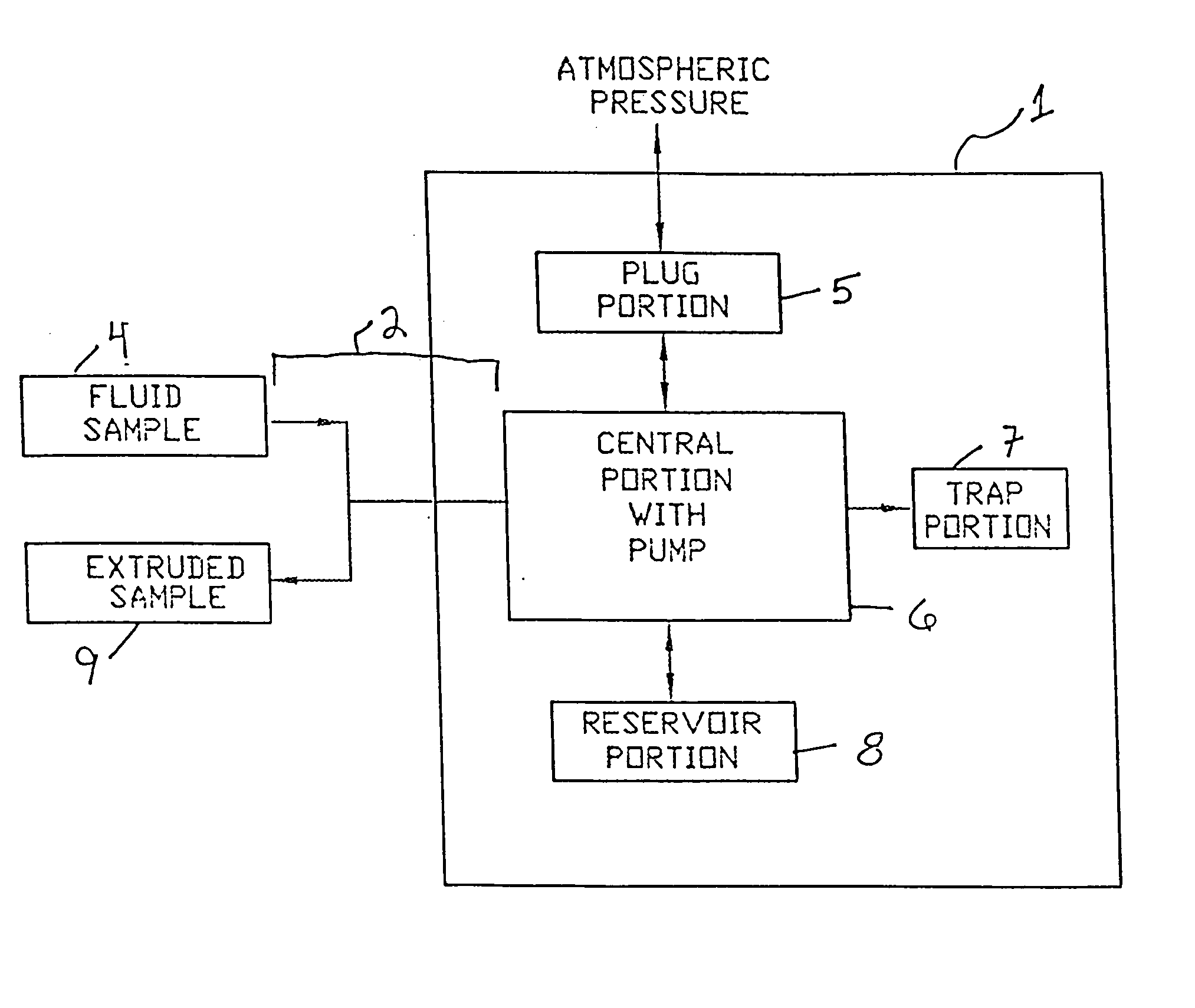
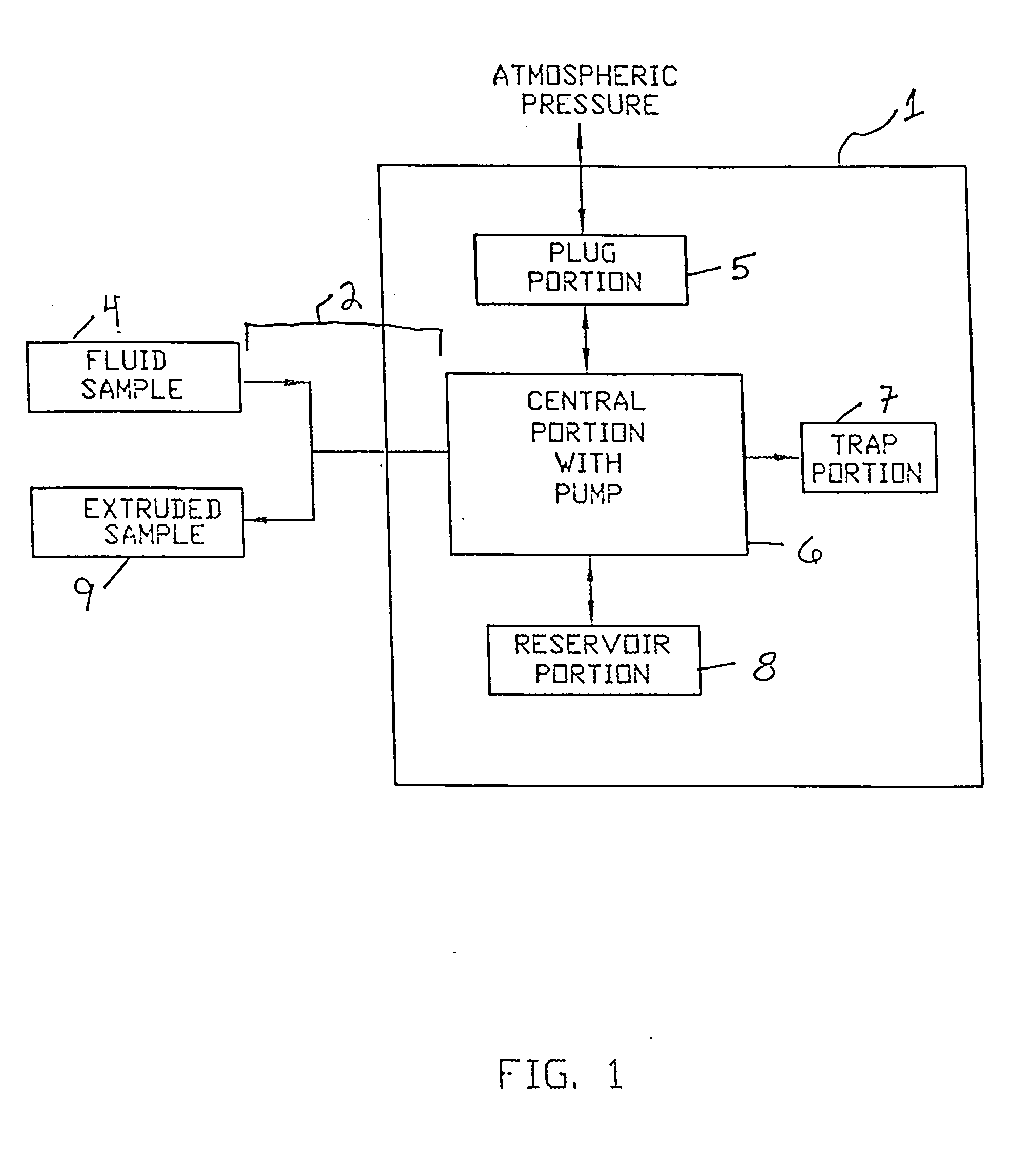
[0021] The sample collection device of the invention includes generally a receptacle body portion 1, a conduit portion 2, and optionally, an attachment portion 3. FIG. 1 is a flow diagram illustrating the functional portions of the sample collection device of the invention. Fluid sample is drawn into the central portion 6 of receptacle portion 1 through conduit portion 2. Generally, central portion 6 includes functionally a space for collecting and mixing the fluid sample 4, and for actuating a mechanism for expelling extruded sample fluid 9 from the device, again via conduit portion 2. Plug portion 5 ensures that central portion 6 is at atmospheric pressure when fluid sample is being collected and drawn into the device, and ensures that central portion 6 is sealed off from atmospheric contact when fluid is being extruded from the device. Trap portion 7 functions as a region for sequestering components that are separated from the fluid sample during centrifugation of the device. Res...


PUM

PropertyMeasurementUnit
volumeaaaaaaaaaa
volumesaaaaaaaaaa
diameteraaaaaaaaaa

Abstract

The invention features a single tool for collecting a known volume of a fluid biological sample from an animal, such as a human or small mammal, for mixing the sample with a predetermined amount of a reagent or a diluent, physically separate components of the sample, for storing the sample in a secure and stable fashion, and for then recovering some or all of the sample in a condition suitable for performing a diagnostic assay. The tool can be equipped with an optional means of recording or displaying information about the sample, such as a tag, a bar code, or a surface indicator that identifies, e.g., the date, animal number, and any additional information necessary. A second bar coded label to remove and attaché to the cage shall be provided. The cage / blood-sample can be correlated if needed at a later date.

Description

REFERENCE TO PRIOR APPLICATION [0001] This application is based on and claims priority from U.S. Provisional Patent Application Ser. No. 60 / 539,819, filed Jan. 28, 2004, which is hereby incorporated by reference.FIELD OF THE INVENTION [0002] This invention relates to a device and method for obtaining a sample of biological fluid. BACKGROUND OF THE INVENTION [0003] The availability of increasingly sensitive biological assays has made it possible to run accurate diagnostic tests on biological samples of very small volume. Obtaining a small fluid sample from an individual, for example 100 microliters (μl) or less, can be a difficult task. Where the individual is a human patient, small volumes of blood are conventionally removed by finger puncture, the finger pricked with a lancet and then squeezed until a fluid drop of, e.g., 10-20 μl, is obtained. When collecting fluid samples from a small mammal, for example, a blood sample from a mouse or rat, the underside of the animal's tail is n...

Claims


Application Information

Patent Timeline
Patent Type & Authority Applications(United States)
IPC IPC(8): A61B5/15B01L3/00G01N1/10
CPCA61B5/1411B01L3/502715B01L3/502723B01L3/50273B01L2400/0688B01L2300/021B01L2400/0406B01L2400/0409B01L2400/0481B01L2200/027A61B5/150022A61B5/150213A61B5/150251A61B5/150343A61B5/150351A61B5/150755A61B5/150786A61B5/150969
Inventor MONTAGU, JEAN
Owner AVANTRA BIOSCI CORP
Learn More