
Communication device and communication device ringing method

a communication device and ringing technology, applied in the field of communication equipment units, can solve the problems of user discomfort, user may find initial difficulty in hearing music, and annoying sound, and achieve the effect of reducing discomfort for users, simplifying the steps for incoming call alerts, and increasing sound volum

Inactive Publication Date: 2005-08-11
MITSUBISHI ELECTRIC CORP
View PDF3 Cites 9 Cited by
  • Summary
  • Abstract
  • Description
  • Claims
  • Application Information

AI Technical Summary

Benefits of technology

[0018] In accordance with this aspect of the invention, the main incoming call alert sound is produced after a predetermined period of time elapses since the production of the advance incoming call alert sound. Accordingly, the user is capable of recognizing the incoming call when the incoming call alert sound having a sound quality and a sound volume corresponding to the mode of usage is produced. In comparison with a situation where a single incoming call alert sound is produced, discomfort felt by the user is reduced. In further accordance with this aspect, incoming call alert is implemented only by a construction related to sound production. In comparison with a case where an alert is given of an incoming call using vibration and then an incoming call alert sound is produced, the construction for incoming call alert is simplified.
[0020] In accordance with this aspect of the invention, the sound volume of the main incoming call alert sound and the advance incoming call alert sound is adjusted so as to reduce discomfort felt by the user.
[0022] In accordance with this aspect of the invention, an incoming call alert signal is prevented from being abruptly produced at a large sound volume, thereby reducing discomfort felt by the user.
[0024] In accordance with this aspect of the invention, the incoming call alert sound comprising the advance incoming call alert sound and the main incoming call alert sound is produced through a single sound generator, thereby simplifying a construction.
[0028] In accordance with this aspect of the invention, the main incoming call alert sound is produced after a predetermined period of time elapses since the advance incoming call alert sound is produced. Therefore, the user is capable of recognizing the incoming call by the incoming call alert sound having a sound quality and a sound volume corresponding to the mode of usage. In comparison with a situation where a single incoming call alert sound is gradually increased in sound volume, discomfort felt by the user is reduced. Incoming call alert is implemented only by steps related to sound production. Therefore, in comparison with a case where an alert is given of an incoming call using vibration and then an incoming call alert sound is produced, the steps for incoming call alert is simplified.

Problems solved by technology

A problem with the related-art incoming call alert using sound in a communication equipment unit is that the sound may be annoying to the user.
However, in the related-art incoming call alert for communication units, the user may still feel uncomfortable as a result of merely changing the sound volume of a single incoming call alert sound, because, with this approach, the user may more or less be surprised at an unexpected incoming call alert sound produced close to the ear.
Here again, the problem according to the related-art incoming call alert using sound in a communication equipment unit is that the only selection available is to set the sound volume of music (incoming call alert sound) at a relatively small level initially and then gradually change it to a normal level, or to set the sound volume at a relatively large, normal level from the beginning.
By selecting incoming call alert in which the sound volume of music is set at a relatively small level initially and then changed gradually to a relatively large, normal level, the user may find initial difficulty in hearing the music.
Either selection of control cannot satisfy the user.
Thus, the related-art incoming call alert using sound in a communication equipment unit may make the user feel uncomfortable when the incoming call alert sound is controlled such that the user can hear it at a relatively large, normal sound volume from the beginning.

Method used


Image

  • Communication device and communication device ringing method
  • Communication device and communication device ringing method
  • Communication device and communication device ringing method

Examples


first embodiment

[0040] A description will now be given of the first embodiment.

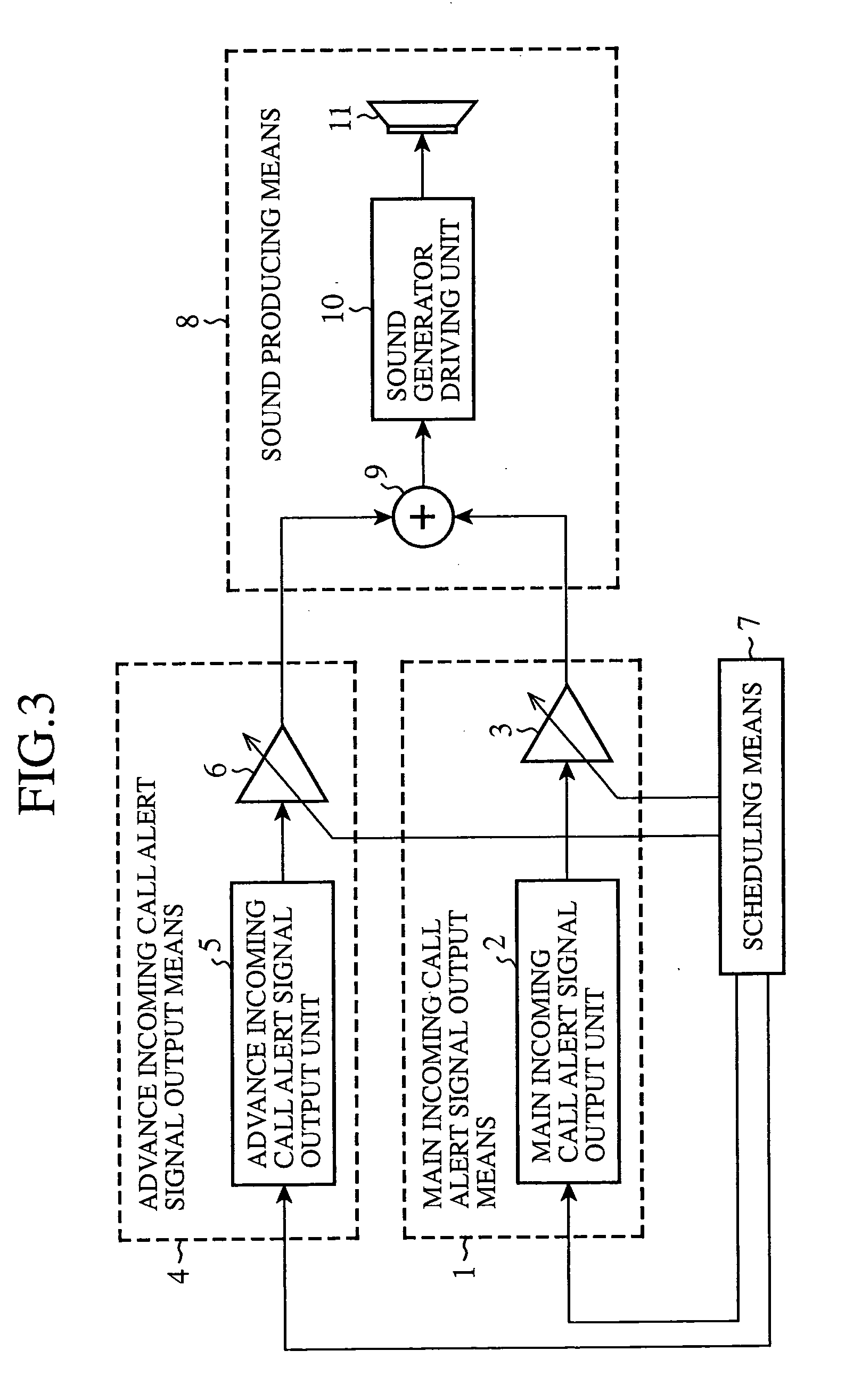
[0041]FIG. 3 shows prime constituents related to incoming call sound alert in a communication equipment unit according to the first embodiment essentially.

[0042] Referring to FIG. 3, a main incoming call alert signal output means 1 outputs a main incoming call alert signal for producing a main incoming call alert sound. The main incoming call alert signal output means 1 according to the first embodiment comprises a main incoming call alert signal output unit 2 for outputting the main incoming call alert signal and a main incoming call alert signal gain adjusting unit 3 for adjusting the gain of the main incoming call alert signal output from the main incoming call alert signal output unit 2.

[0043] An advance incoming call alert signal output means 4 outputs an advance incoming call alert signal for producing an advance incoming call alert sound produced in advance of the main incoming call alert sound and different fr...

second embodiment

[0078] A description will be given of the second embodiment.

[0079] In the first embodiment, the scheduling means outputs an output start signal to the main incoming call alert signal output unit and subsequently outputs an output start signal to the advance incoming call alert signal output unit at a timing preset based on a predetermined period of time. A description will now be given of the second embodiment in which the output start signal is simultaneously output to the main incoming call alert signal output unit and the advance incoming call alert signal output unit.

[0080] The main construction according to the second embodiment related to incoming call alert in a communication equipment unit is as shown in FIG. 3. Since the construction remain unchanged, the description thereof is omitted.

[0081] A difference in the operation schedule is that the main incoming call alert signal and the advance incoming call alert signal are timed to be output simultaneously. The gain is set ...

third embodiment

[0096] A description will now be given of the third embodiment.

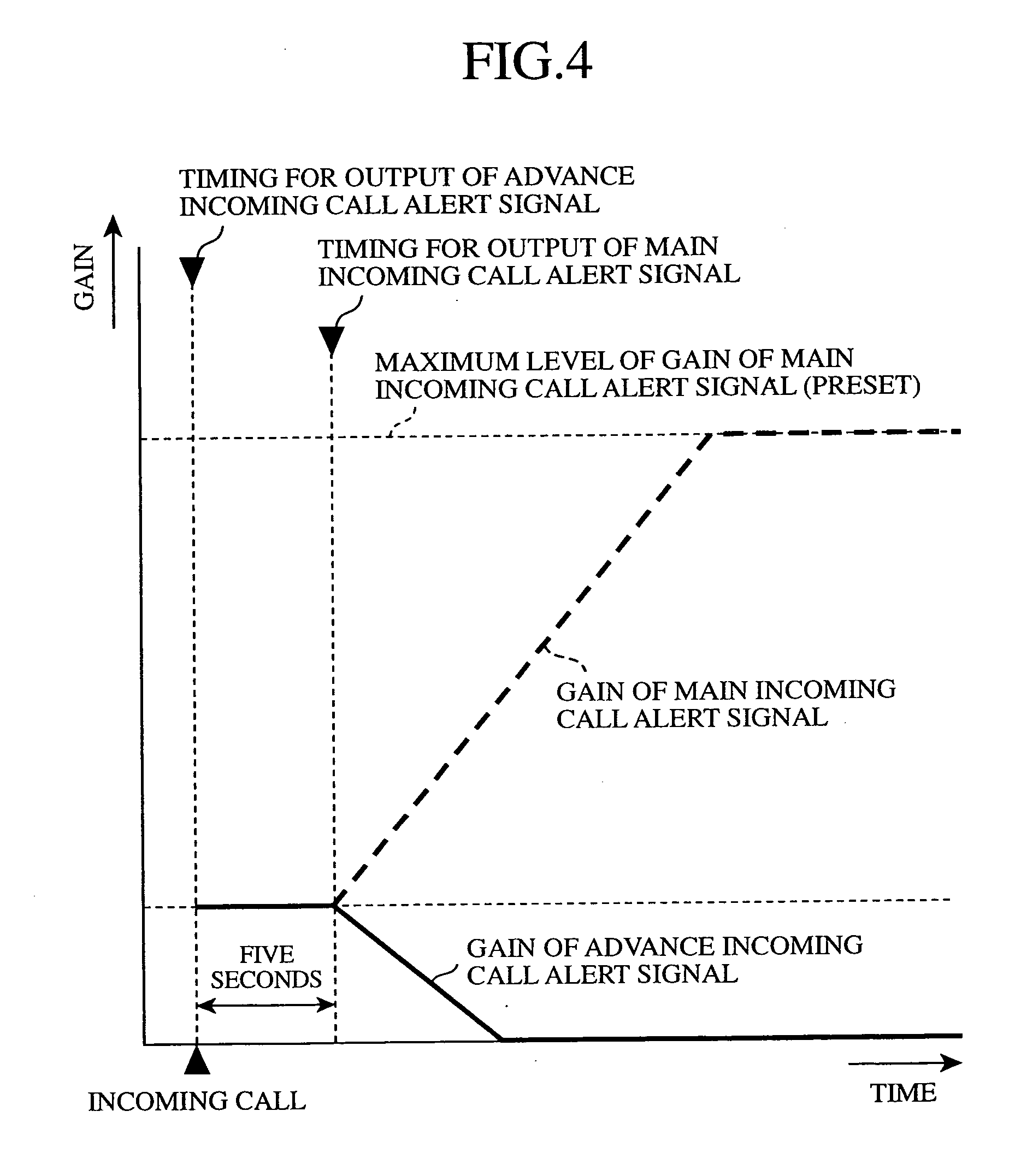
[0097] In the foregoing embodiments, a description is given of a situation where, in response to an incoming call, only the advance incoming call alert sound at a relatively small sound volume is produced initially. Subsequently, the main incoming call alert sound grows in sound volume, and the advance incoming call alert sound fades out. The third embodiment employs another pattern for sounding an incoming call alert sound.

[0098] A main construction related to incoming call alert in a communication equipment unit according to the third embodiment is shown in FIG. 3. Since the construction is the same as that of the first embodiment, the description thereof is omitted.

[0099] A difference is that the operation schedule is set as shown in FIG. 9.

[0100] In the third embodiment, the communication equipment unit operates as shown in FIG. 5 illustrating the operation according to the first embodiment. Since the operation s...


PUM


Abstract

A communication equipment unit producing an incoming call alert sound includes: main incoming call alert signal output means for outputting a main incoming call alert signal for sounding a main incoming call alert sound; advance incoming call alert signal output means for outputting an advance incoming call alert signal for sounding an advance incoming call alert sound; scheduling means for allowing the main incoming call alert signal output means and the advance incoming call alert signal output means to operate so that the main incoming call alert sound is produced after a predetermined period of time elapses since the advance incoming call alert sound is produced; and sound production means reducing the incoming call alert sound based on the main incoming call alert signal and the advance incoming call alert signal.

Description

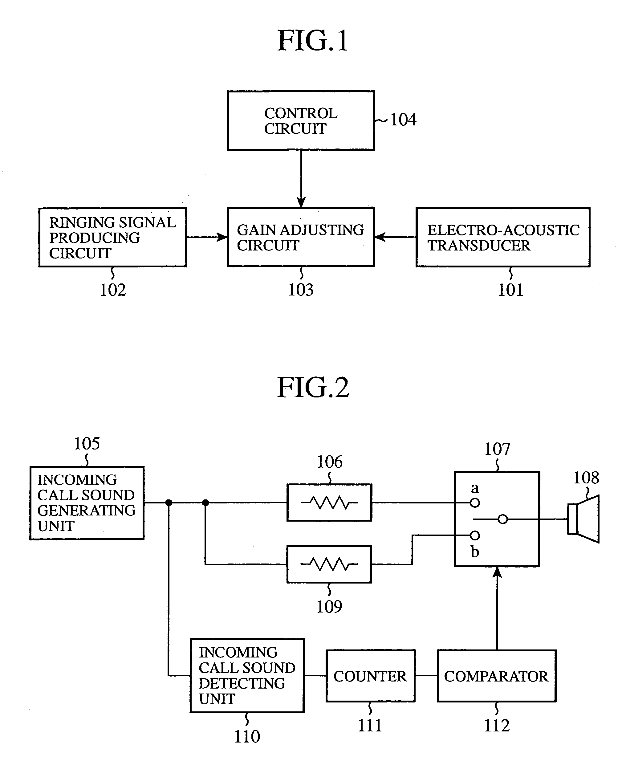
TECHNICAL FIELD [0001] The present invention relates to communication equipment units including fixed (wired) telephones, portable telephones, and wireless communication units for institutional use. The invention relates more particularly to communication equipment units and an incoming call alert method for communication equipment units that generate an incoming call alert sound to a user (individual, or a plurality of persons using a terminal) of the communication equipment unit when there is an incoming call from a communication equipment unit requesting communication. BACKGROUND ART [0002] For communication between a plurality of communication equipment units, there is used a method for generating an incoming call alert sound for notifying a user of communication equipment unit of an incoming call from another communication equipment unit. [0003]FIG. 1 is a schematic diagram showing an exemplary wireless communication unit disclosed in Japanese Laid-Open Patent Application No. 1...

Claims


Application Information

Patent Timeline
IPC IPC(8): H04M19/04H04M1/00
CPCH04M19/04
Inventor MATSUOKA, BUNKEITAKAHASHI, SHINYA
Owner MITSUBISHI ELECTRIC CORP
Learn More