Display device
a display panel and display technology, applied in the field of displays, can solve the problems of limited basic functions, poor low-frequency performance of piezoelectric ceramics, and poor sound technology of piezoelectric ceramics, so as to improve user privacy, improve the effect of sound directivity, and improve the effect of display panel
- Summary
- Abstract
- Description
- Claims
- Application Information
AI Technical Summary
Benefits of technology
Problems solved by technology
Method used
Image
Examples
embodiment 1
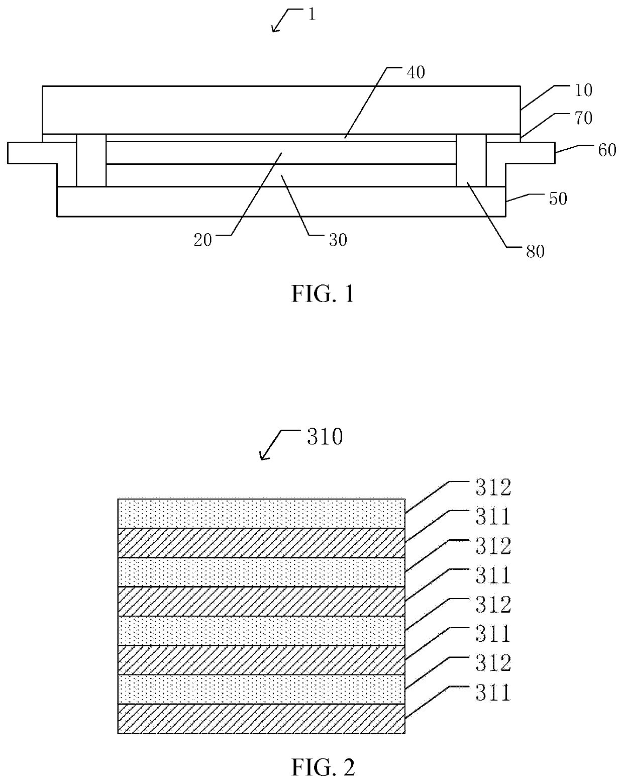
[0027]The present application provides a display device 1. As shown in FIG. 1, the display device 1 includes a display panel 10, a vibration plate 20, and an actuator structural layer 30. The vibration plate 20 is attached to a side of the display panel 10. The actuator structural layer 30 is disposed on the vibration plate 20.
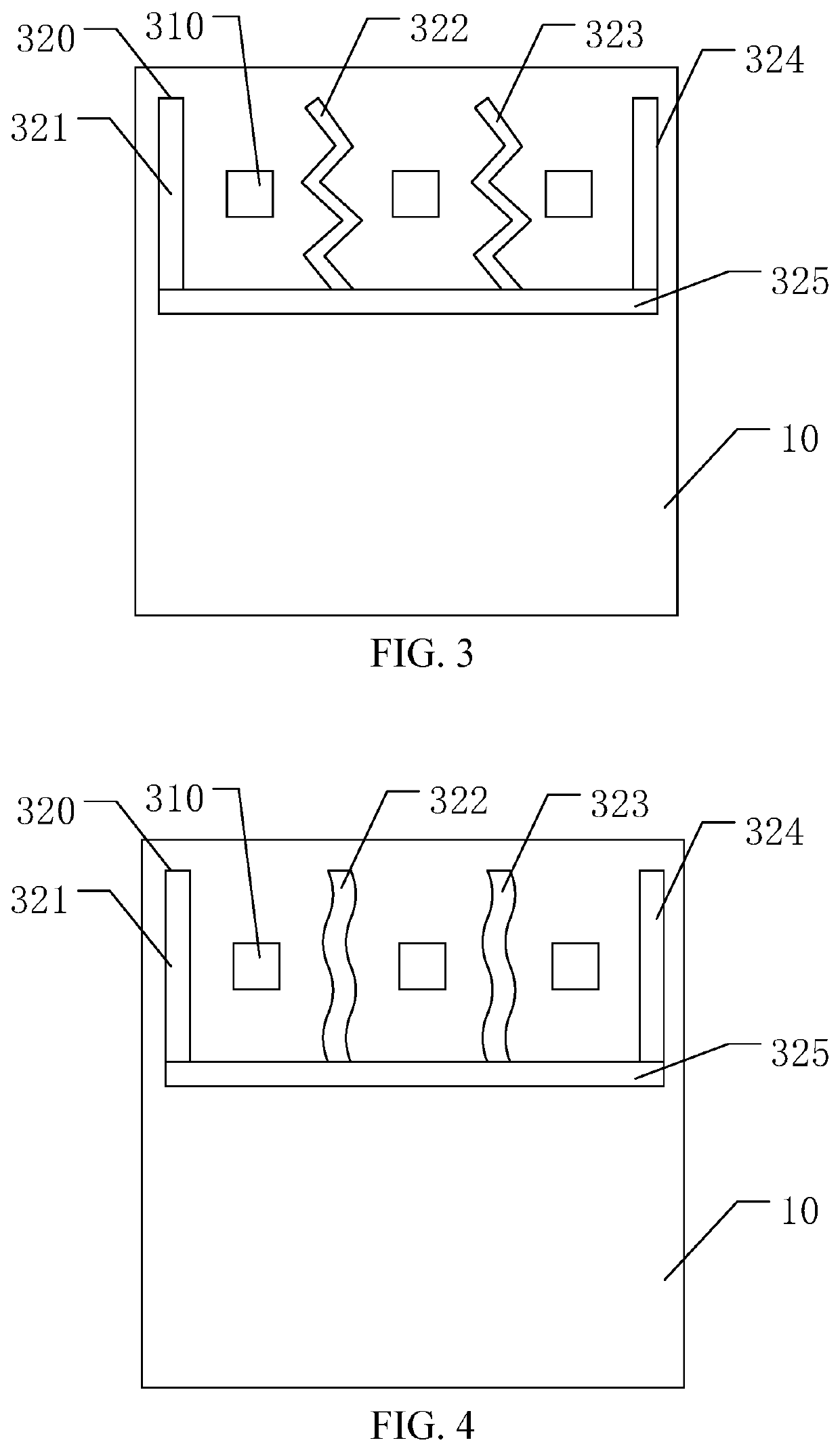
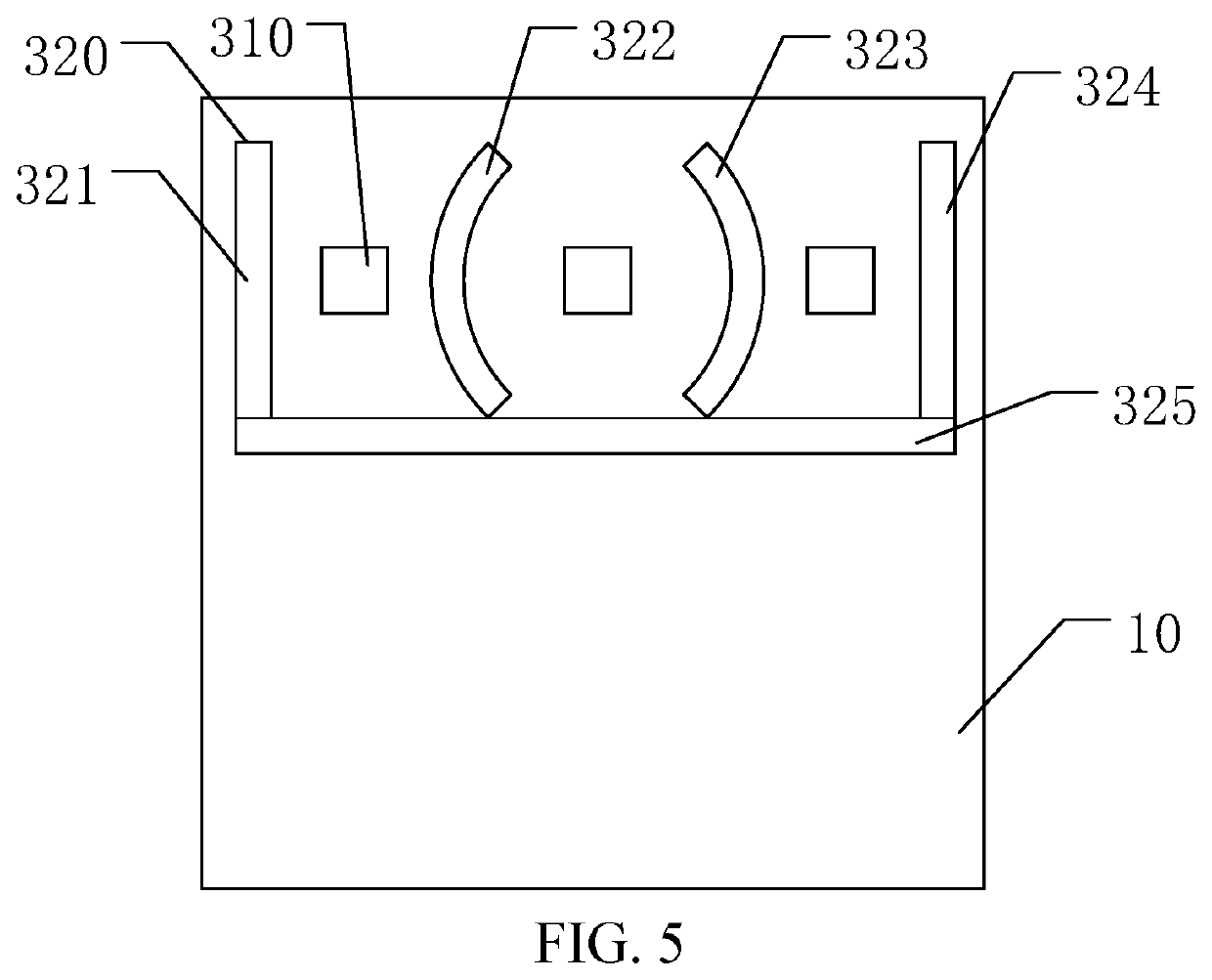
[0028]The actuator structural layer 30 includes a vibrator 310 and a soundproof layer 320. As shown in FIG. 2, the vibrator 310 is embodied by a multilayer piezoelectric ceramic wafer, including an electrode layer 311 and a piezoelectric layer 312. The electrode layer 311 and the piezoelectric layer 312 are alternately disposed in an overlapping arrangement. The piezoelectric layer 312 is made of one of lead zirconate titanate (PZT), aluminum nitride (AlN), polyvinylidene fluoride (PVDF), and polyvinylidene fluoride-trifluoroethylene copolymer (P(VDF-TrFE)). When an alternating voltage is applied to the electrode layer 311, the piezoelectric layer 312 vibrates...
embodiment 2
[0036]The present application provides a display device 1. As shown in FIG. 1, the display device 1 includes a display panel 10, a vibration plate 20, and an actuator structural layer 30. The vibration plate 20 is attached to a side of the display panel 10. The actuator structural layer 30 is disposed on the vibration plate 20.
[0037]The actuator structural layer 30 includes a vibrator 310 and a soundproof layer 320. As shown in FIG. 2, the vibrator 310 is embodied by a multilayer piezoelectric ceramic wafer, including an electrode layer 311 and a piezoelectric layer 312. The electrode layer 311 and the piezoelectric layer 312 are alternately disposed in an overlapping arrangement. The piezoelectric layer 312 is made of one of lead zirconate titanate (PZT), aluminum nitride (AlN), polyvinylidene fluoride (PVDF), and polyvinylidene fluoride-trifluoroethylene copolymer (P(VDF-TrFE)). When an alternating voltage is applied to the electrode layer 311, the piezoelectric layer 312 vibrates...
embodiment 3
[0045]The present application provides a display device 1. As shown in FIG. 1, the display device 1 includes a display panel 10, a vibration plate 20, and an actuator structural layer 30. The vibration plate 20 is attached to a side of the display panel 10. The actuator structural layer 30 is disposed on the vibration plate 20.
[0046]The actuator structural layer 30 includes a vibrator 310 and a soundproof layer 320. As shown in FIG. 2, the vibrator 310 is embodied by a multilayer piezoelectric ceramic wafer, including an electrode layer 311 and a piezoelectric layer 312. The electrode layer 311 and the piezoelectric layer 312 are alternately disposed in an overlapping arrangement. The piezoelectric layer 312 is made of one of lead zirconate titanate (PZT), aluminum nitride (AlN), polyvinylidene fluoride (PVDF), and polyvinylidene fluoride-trifluoroethylene copolymer (P(VDF-TrFE)). When an alternating voltage is applied to the electrode layer 311, the piezoelectric layer 312 vibrates...
PUM
 Abstract
Description
Claims
Application Information
 - R&D
- Intellectual Property
- Life Sciences
- Materials
- Tech Scout
- Unparalleled Data Quality
- Higher Quality Content
- 60% Fewer Hallucinations
Browse by: Latest US Patents, China's latest patents, Technical Efficacy Thesaurus, Application Domain, Technology Topic, Popular Technical Reports.
© 2025 PatSnap. All rights reserved.Legal|Privacy policy|Modern Slavery Act Transparency Statement|Sitemap|About US| Contact US: help@patsnap.com


