
Distributed adaptive repeater system

Inactive Publication Date: 2005-08-11
SPOTWAVE WIRELESS INC
View PDF9 Cites 101 Cited by
  • Summary
  • Abstract
  • Description
  • Claims
  • Application Information

AI Technical Summary

Benefits of technology

[0016] An object of the present invention is to provide an method and system for providing reliable wireless service within severe RF environments.

Problems solved by technology

For example, within a building, or a built-up urban area, signal attenuation, shadowing by buildings and / or hills; noise generated by various radio frequency sources, and multi-path effects can seriously degrade the quality of desired RF signals.
This delay is inherent to the amplification process, but is caused primarily by band-pass filters used in the repeater to prevent the unwanted amplification of signals outside the frequency band of interest.
As is well known in the art, on-frequency repeaters suffer a limitation in that the output signal (So) can feed back to the input antenna via a so-called “leakage path”.
However, if the system gain (G) becomes too high, so that Sf≧Se, then signal leakage between the output and input antennas will cause system oscillation.
However, in practice, the antenna isolation is difficult to predict, and will frequently change over time.
This high (10-15 db) margin between antenna isolation and system gain is commonly achieved by limiting and sacrificing system gain, which significantly decreases the sensitivity (and thus efficiency) of the repeater.
As is well known in the art, the provision of adequate wireless services within buildings can pose particularly difficult problems.
This is typically due to shielding effects of building walls; jamming due to RF emissions from equipment (such as motors, electronic devices etc.) within the building; and severe multi-path fade.
These systems tend to be expensive, and suffer high losses.
However, because, every coverage antenna necessarily radiates the same RF signal, spatial nulls are created at locations where RF signals radiated from different coverage antennas have equal amplitude and a phase difference of 180°.
These spatial nulls are substantially stationary, and can severely disrupt wireless communications.
An additional problem encountered with multiple coverage antennas is that some of the energy radiated by each coverage antenna (i) will appear at the donor antenna as a feedback signal Sfi.
In some cases, the presence of multiple feedback signals Sfi at the repeater input can defeat the antenna isolation detection and monitoring system entirely, thereby rendering the repeater inoperative.

Method used


Image

  • Distributed adaptive repeater system
  • Distributed adaptive repeater system
  • Distributed adaptive repeater system

Examples


Embodiment Construction

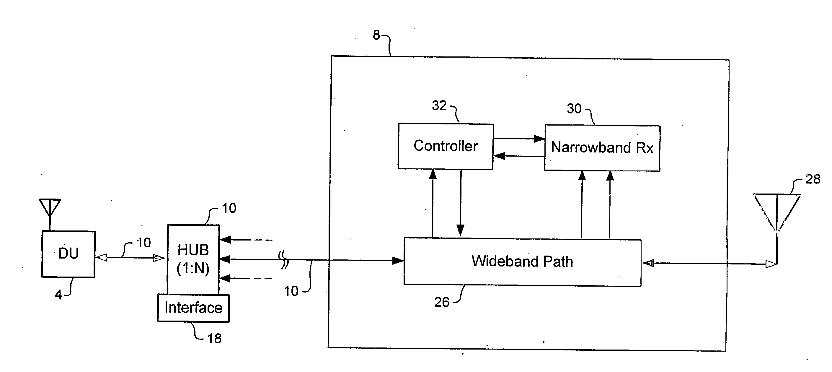
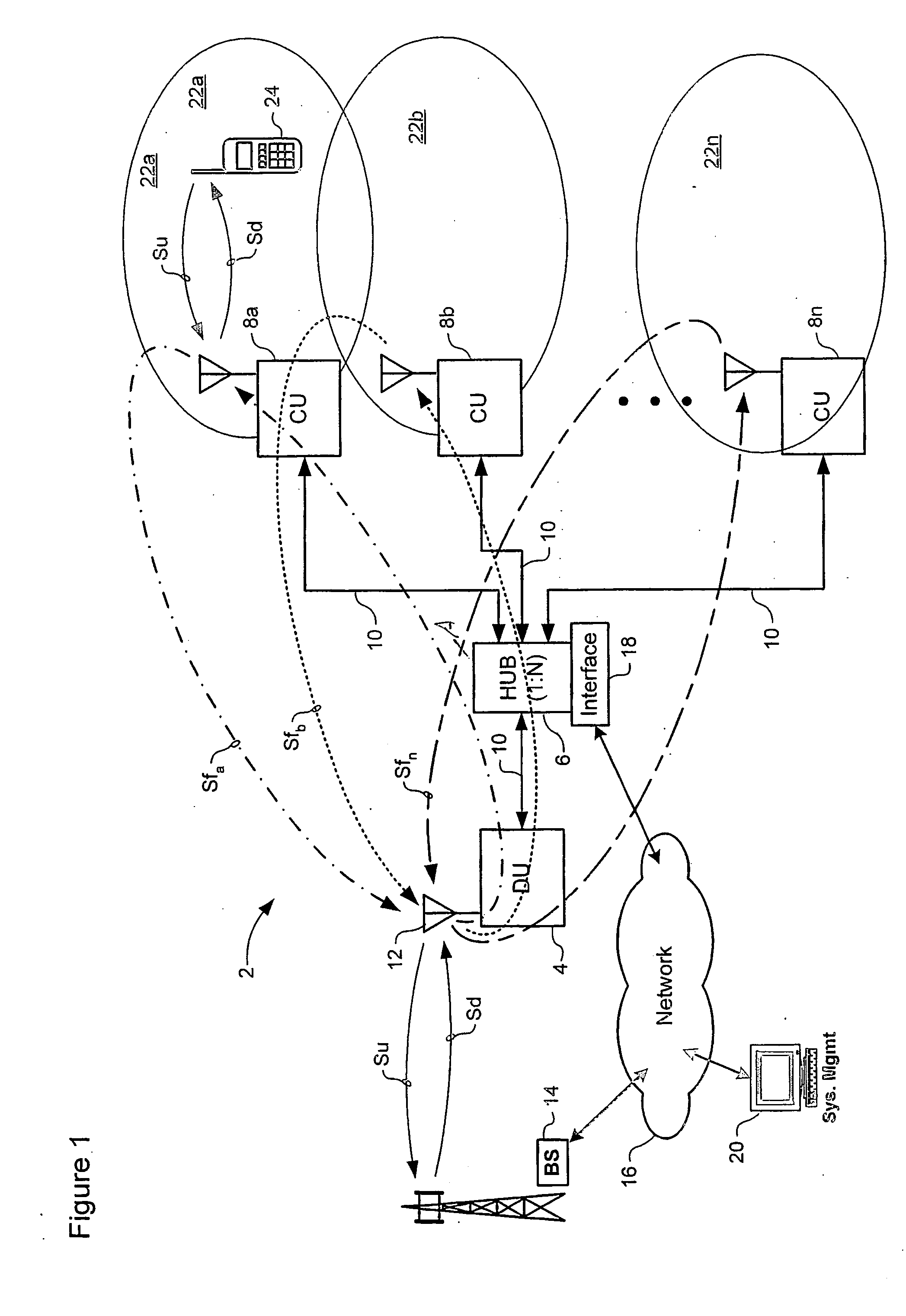
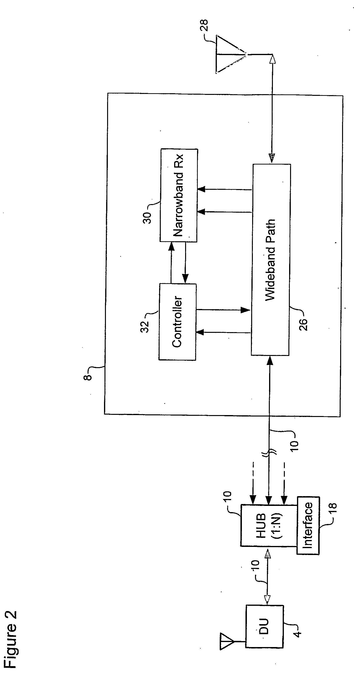
[0025] The present invention provides a cost effective system for providing reliable wireless services within a severe RF environment, such as, for example, within the interior of a building. FIG. 1 is a is a block diagram schematically illustrating principle elements of an on frequency repeater in accordance with the present invention.

[0026] As shown in FIG. 1, the repeater 2 generally comprises a donor unit (DU) 4, an intelligent hub 6, and two or more coverage units (CUs) 8. Conventional transmission lines 10, such as RG-58 or RG-6 co-axial cable, are used to convey signals between the donor unit 4, the hub 6, and each of the coverage units 8.

[0027] The donor unit comprises a donor antenna 12 integrated with a bidirectional amplifier (not shown), which provides sufficient gain to overcome losses in the cable 10 and the intelligent hub 6. This arrangement enables the use of low cost co-axial cable, thereby reducing the overall system cost, and simplifying installation. In genera...


PUM


Abstract

A distributed adaptive repeater system includes a donor unit, two or more coverage units (CUs), and an intelligent hub. The donor unit operates to maintain bidirectional wireless communication with a base station of a wireless communications network. Each coverage unit maintains bidirectional wireless communication with transceivers located within a respective coverage area, and is further adapted to independently control a signal path gain to ensure stability of a respective feedback loop to the donor unit. Finally, the intelligent hub is operatively coupled between the donor unit and the coverage units, and adapted to monitor a status of each coverage unit.

Description

CROSS-REFERENCE TO RELATED APPLICATIONS [0001] This is the first application filed for the present invention. MICROFICHE APPENDIX [0002] Not Applicable. TECHNICAL FIELD [0003] The present application relates to wireless access networks and, in particular, to distributed adaptive repeater system. BACKGROUND OF THE INVENTION [0004] On-frequency repeaters are known in the art for improving wireless services within defined regions of a wireless network, where signal levels would otherwise be too low for satisfactory quality of service. For example, within a building, or a built-up urban area, signal attenuation, shadowing by buildings and / or hills; noise generated by various radio frequency sources, and multi-path effects can seriously degrade the quality of desired RF signals. In some cases, a wireless network provider may install a repeater in order to improve service in a region lying at an edge of the coverage area serviced by a base station, thereby effectively extending the reach ...

Claims


Application Information

Patent Timeline
IPC IPC(8): H04B7/15H04W88/08
CPCH04W88/085H04B7/15578
Inventor YOUNG, SHANEROPER, MIKEZHANG, JIEALLEN, STEVESIMPSON, PAULKELLETT, COLIN
Owner SPOTWAVE WIRELESS INC
Learn More