
Segmented ball/roller guide for a linear motion bearing

a linear motion bearing and guide assembly technology, applied in the direction of bearings, shafts and bearings, bearings, etc., can solve the problems of reducing the load/life performance of the bearing assembly, difficult and expensive to achieve on the supporting structure, and generating adverse conditions for the bearing

Inactive Publication Date: 2005-08-11
DANAHER MOTION
View PDF14 Cites 12 Cited by
  • Summary
  • Abstract
  • Description
  • Claims
  • Application Information

AI Technical Summary

Benefits of technology

[0016] Accordingly, it is an objective of the present invention to provide a new ball-to-ball separator technology, which will eliminate the disadvantages of the prior art rolling element chains and ball spacers.
[0017] It is another object of the present invention to provide a segmented ball / roller guide for eliminating ball-to-ball contact in linear motion bearings.
[0018] It is a further object of the present invention to provide a segmented ball / roller guide for reducing mechanical and / or acoustic vibrations in linear motion bearings.
[0019] It is yet another object of the present invention to provide a segmented ball / roller guide which allows greater flexibility in designing return track geometry.

Problems solved by technology

In addition this precise alignment also minimizes skewing forces acting on the bearing assembly, which skewing forces tend to reduce the load / life performance of the bearing assembly.
In such installations, considerable precision machining of the supported structure is necessitated which is difficult and expensive to accomplish on the supporting structures.
Typically, in the linear bearing assemblies, as disclosed in the above-identified patents, the ball-to-ball contact in the ball track generates adverse conditions when the bearing is in operation.
The rolling element chain does not provide designers with much freedom in designing ball track geometry.
This restricts the location of the return track geometry for the ball track and often results in an unwanted outside bearing envelope dimension increase or modification due to the location of return geometry for the rolling elements.
However, this is a very undesirable design due to long term effects on the material when it is twisted constantly.
If the spacers are dropped out of its position between the balls to the bottom or sides of the ball track, they will create severe impediments to linear motion.
This could result in a catastrophic failure on the bearings.

Method used


Image

  • Segmented ball/roller guide for a linear motion bearing
  • Segmented ball/roller guide for a linear motion bearing
  • Segmented ball/roller guide for a linear motion bearing

Examples


Embodiment Construction

[0033] Preferred embodiments of the present invention will be described hereinbelow with reference to the accompanying drawings. In the following description, well-known functions or constructions are not described in detail to avoid obscuring the invention in unnecessary detail. It is provided that identical elements are structurally and functionally equivalent throughout the drawings.

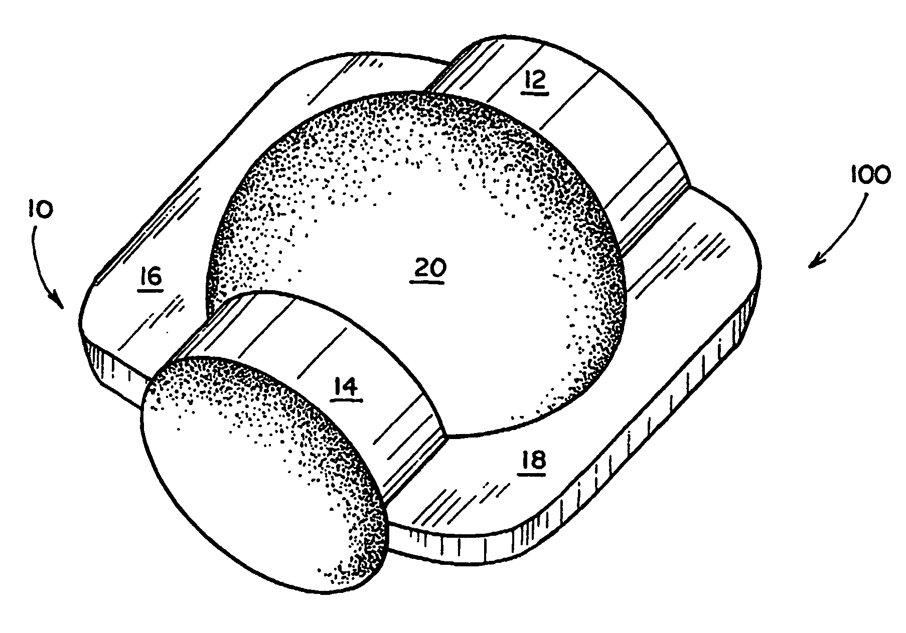
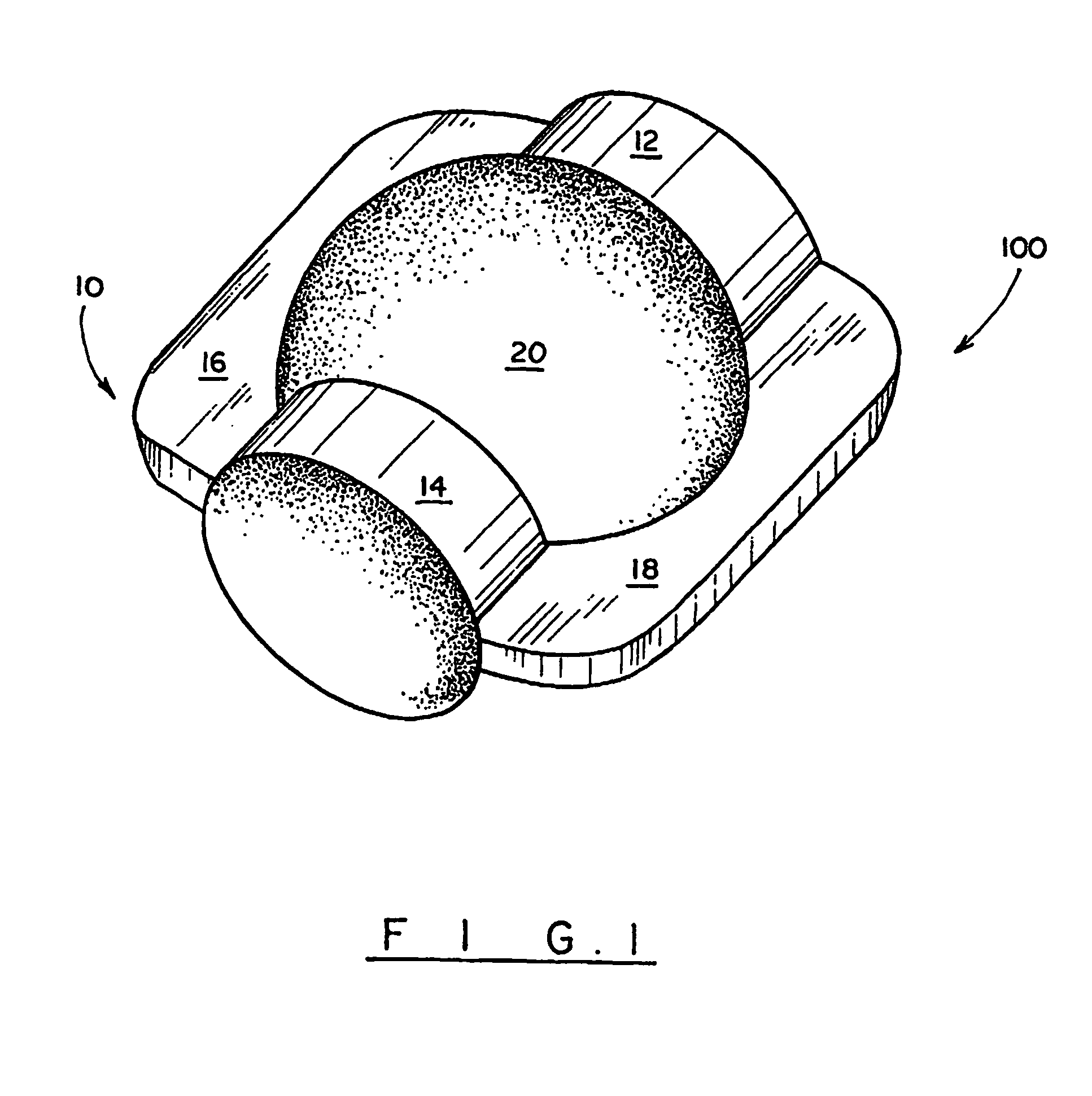
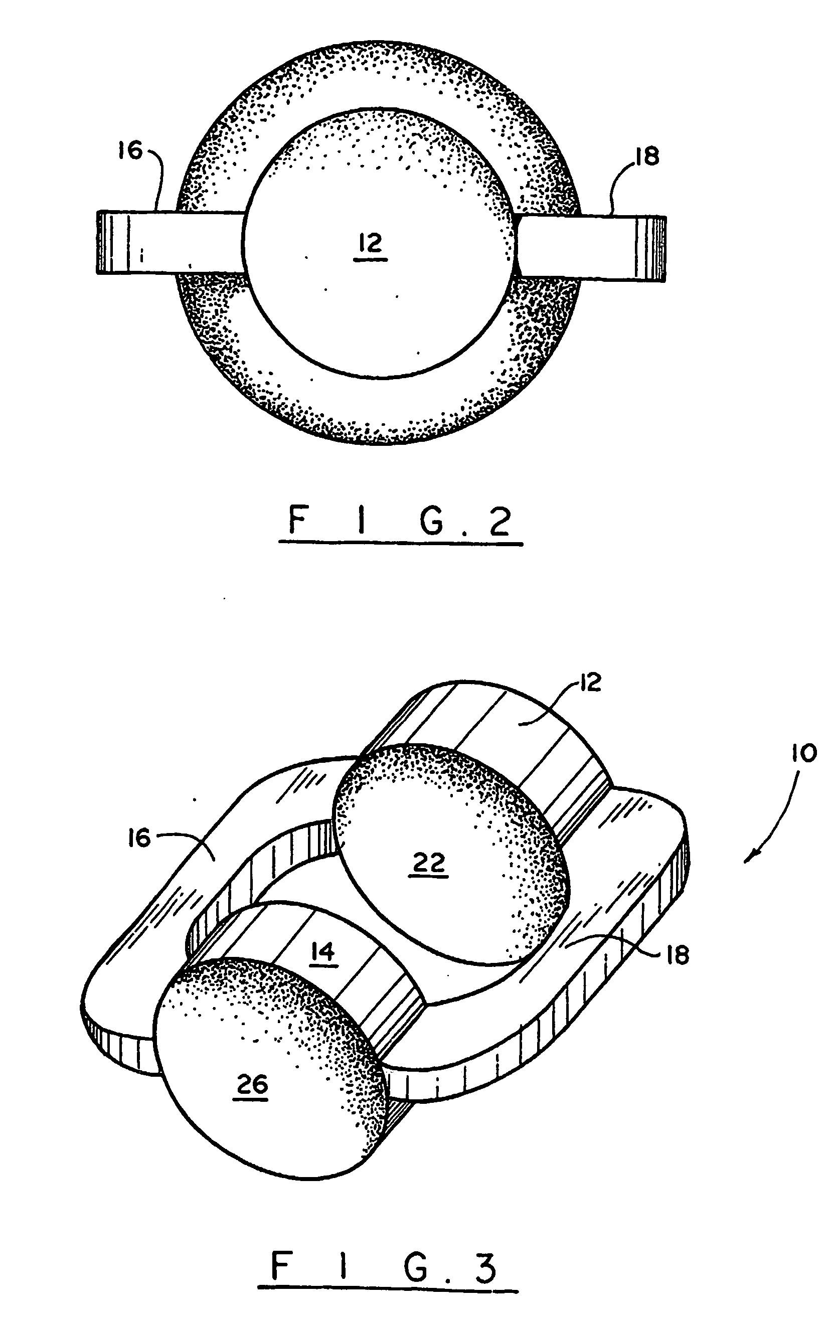
[0034] Referring to the FIGS. 1-8, a segmented ball / roller guide in accordance with the present invention is identified generally by the reference numeral 10.

[0035]FIGS. 1-5 illustrates a segmented ball / roller guide assembly 100 with a ball bearing contained therein. The segmented ball / roller guide 10 of the present invention includes at least one first spacer member 12. While the first spacer member 12 can completely or partially surround a rolling element, such as a ball bearing 20, as will be discussed hereinbelow, many of the inventive modifications of the support / guide 10 include a second space...


PUM


Abstract

A guide (10) associated with a linear motion and screw system is configured to at least partially surround one of a plurality of rolling elements (20) so as to prevent ball-to-ball contact between the one rolling element and adjacent rolling elements during displacement of the rolling element along a circulation ball track.

Description

CROSS-REFERENCE TO RELATED APLICATION [0001] This application is based on U.S. Provisional Application No. 60 / 360,155 filed on Feb. 27, 2002 and fully incorporated herein by reference.BACKGROUND OF THE INVENTION [0002] 1. Field of the Invention [0003] The present invention relates generally to anti-friction linear motion bearing assemblies. More particularly, the present invention is directed to a segmented ball / roller guide assembly utilized to eliminate vibrations caused by ball-to-ball contact in linear motion bearings. [0004] 2. Description of the Related Art [0005] Linear bearings or ball screws are well known for their significant reduction in dynamic and static friction versus plain bearings or lead screws under load. There are different types of linear bearings and ball screws offered on the market today. However, they share a common focus to control ball recirculation properly to provide smooth linear or rotary motion. [0006] Typical linear rolling bearing assemblies includ...

Claims


Application Information

Patent Timeline
IPC IPC(8): F16C29/06F16C33/38F16H25/22
CPCF16C29/0685F16H25/2238F16C33/3818F16C29/06F16C33/38F16C33/51F16H25/22
Inventor KIM, ERICKNG, ALISON
Owner DANAHER MOTION
Learn More