Surveillance implementation in managed VOP networks
a technology of managed vop networks and surveillance, applied in data switching networks, instruments, frequency-division multiplexes, etc., can solve the problem of not being able to decrypt packets without security keys
- Summary
- Abstract
- Description
- Claims
- Application Information
AI Technical Summary
Benefits of technology
Problems solved by technology
Method used
Image
Examples
first embodiment
[0174] In a first exemplary embodiment of the invention, FIG. 4A depicts a managed VoP network (10), administered by a service provider, wherein an end-user device (11) (either a PC (11A) or a telephone (11B)) may place or receive packet-based telephone calls either within said network, or alternatively, through said network to a public switched telephone network (PSTN) (12). In the first embodiment, Step 1 of the inventive procedure (analysis of said network) reveals that user device 11 is connected to network 10 via a media gateway (13), an access network (14) and finally an edge router (15). Step 1 also reveals that network 10 further comprises the VoP-capable devices of a call server (16), an audio server (17) and a trunk gateway (31). Finally, the procedure reveals that the entire VoP network 10 is being managed by a network management system (18). Note that calls generally involve two or more parties with two or more end-user devices, gateways and access networks. These additi...
second embodiment
[0184] In a second exemplary embodiment of the invention, FIG. 5A depicts a managed VoP network (100), administered by a service provider, wherein an end-user device (111) (either a PC (111A) or a telephone (111B)) may place or receive packet-based telephone calls either within said network, or alternatively, through said network to a public switched telephone network (PSTN) (112). In the second embodiment, Step 1 of the inventive procedure (analysis of said network) reveals that user device 111 is connected to network 100 via a media gateway (113), an access network (114) and finally an edge router (115). Step 1 also reveals that network 100 further comprises the VoP-capable devices of a call server (116), a centralized media gateway (117) and a trunk gateway (131). Finally, the procedure reveals that the entire VoP network 100 is being managed by a network management system (118). Note that calls generally involve two or more parties with two or more end-user devices, gateways and...
third embodiment
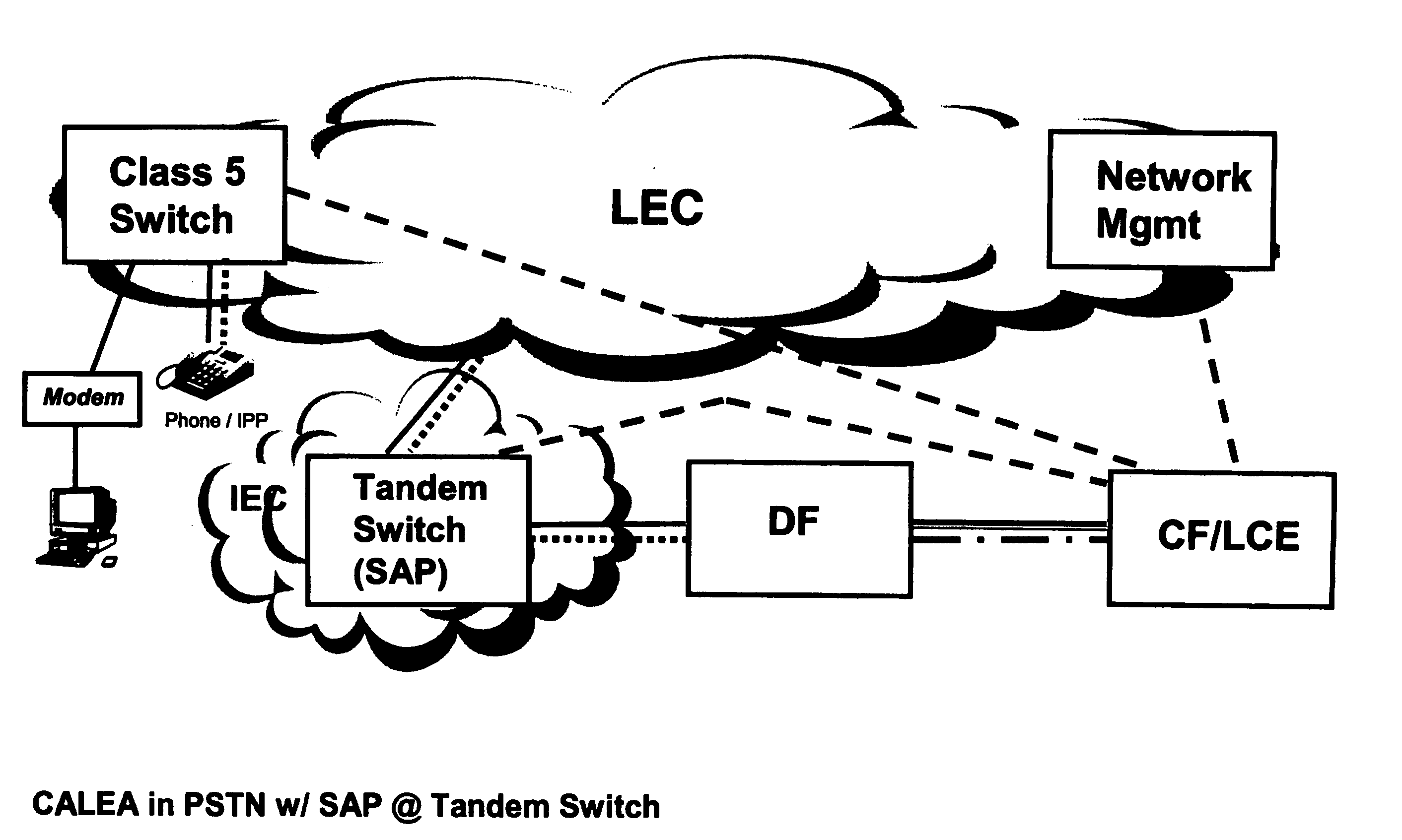
[0197] As a result of the analysis of the network of the third embodiment performed during procedure Step 1 above, media gateway 213 and call server 216 are identified as suitable SAPs during procedure Step 2. The precise nature of said Step 1 analysis and Step 2 SAP identification is beyond the scope of this discussion. Both steps are performed internal to the LEA in cooperation with said service provider. The network analysis and identification of SAPs is based on LEA assumptions regarding the nature and use of the targeted user device 211, the media gateway 213, the access network 214 and the physical and operational features of network 200.
[0198] In Step 3 of the procedure, media gateway 213 and call server 216, collectively, exemplary SAP devices 213 / 216, are configured by the service provider as part of DF 219 to permit interface with CF / LCE 220. In this embodiment, configuration of the media gateway, which may physically exist on the end-user's premises, would have to occur v...
PUM
 Abstract
Description
Claims
Application Information
 - R&D
- Intellectual Property
- Life Sciences
- Materials
- Tech Scout
- Unparalleled Data Quality
- Higher Quality Content
- 60% Fewer Hallucinations
Browse by: Latest US Patents, China's latest patents, Technical Efficacy Thesaurus, Application Domain, Technology Topic, Popular Technical Reports.
© 2025 PatSnap. All rights reserved.Legal|Privacy policy|Modern Slavery Act Transparency Statement|Sitemap|About US| Contact US: help@patsnap.com


