
Super-wide-angle optical system and image pickup device

a wide-angle optical system and image pickup technology, applied in the field of super-wide-angle optical systems, can solve the problems of reducing the number of lenses, reducing the size of the entire length and a diameter of the lens, and unable to achieve downsizing or sufficient definition, etc., and achieve the effect of satisfying optical performan

Active Publication Date: 2005-08-11
KONICA MINOLTA OPTO
View PDF2 Cites 65 Cited by
  • Summary
  • Abstract
  • Description
  • Claims
  • Application Information

AI Technical Summary

Benefits of technology

[0007] It is an object of the present invention to provide an optical system which solves the above problems. Another object of the invention is to provide an inexpensive and compact super-wide-angle optical system having satisfactory optical performance and a wide field angle, an image pickup lens device and a monitor device using the optical system.

Problems solved by technology

When the number of lenses is decreased, various problems arise.
For example as described in Japanese Patent No. 2992547, when the number of lenses is decreased, an entire length and a diameter of the lens become large, downsizing or sufficient definition become difficult.
Further, as described in Japanese Patent Application Laid-Open No. 2002-72085, when the number of lenses is decreased, a diameter of the lenses (particularly, a diameter of a first lens) becomes large, and also the production cost increases due to the use of aspherical glass lenses.

Method used


Image

  • Super-wide-angle optical system and image pickup device
  • Super-wide-angle optical system and image pickup device
  • Super-wide-angle optical system and image pickup device

Examples


examples

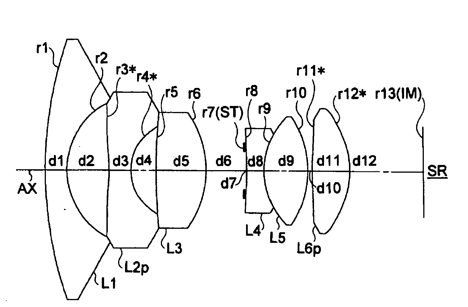
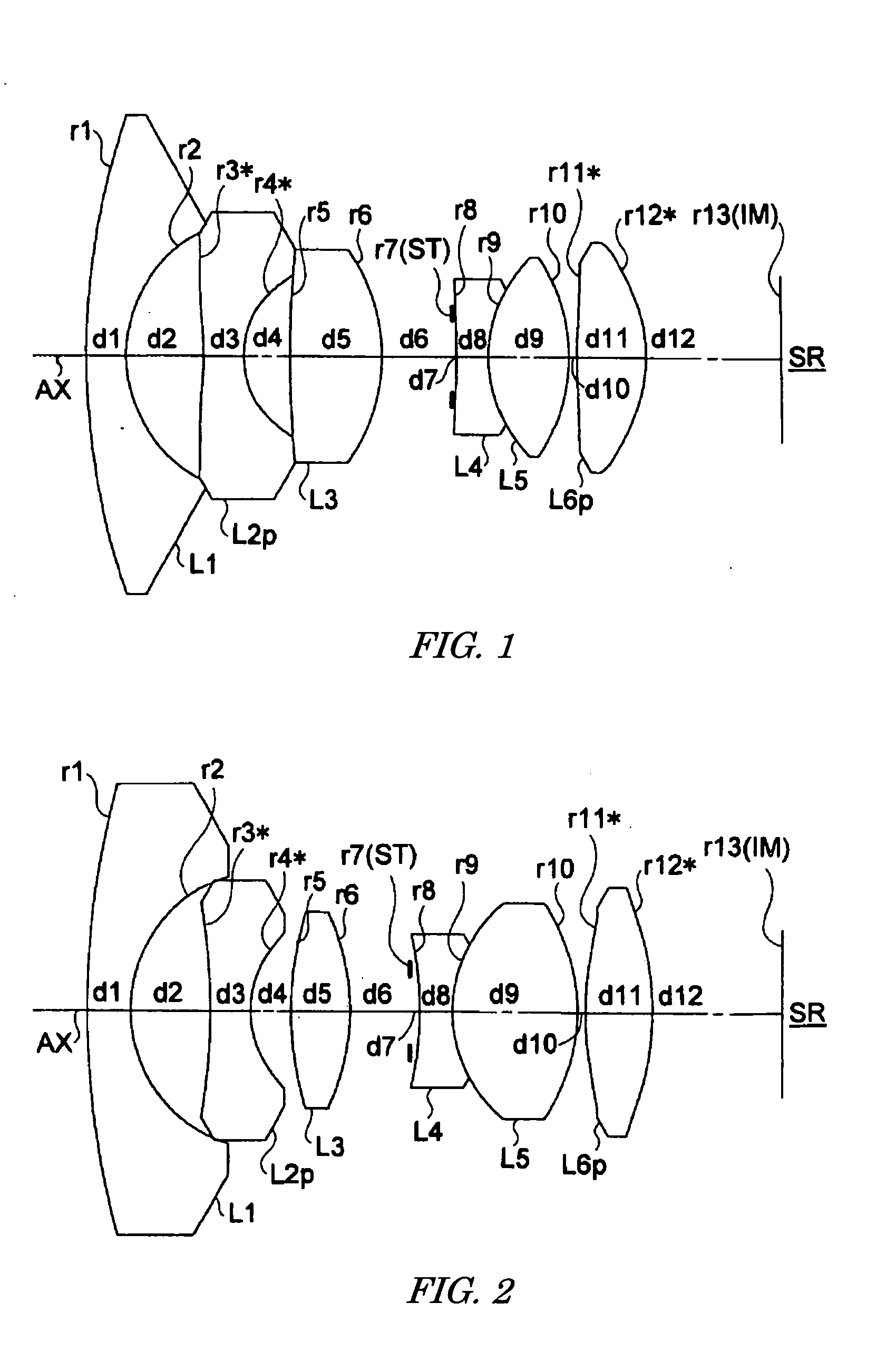
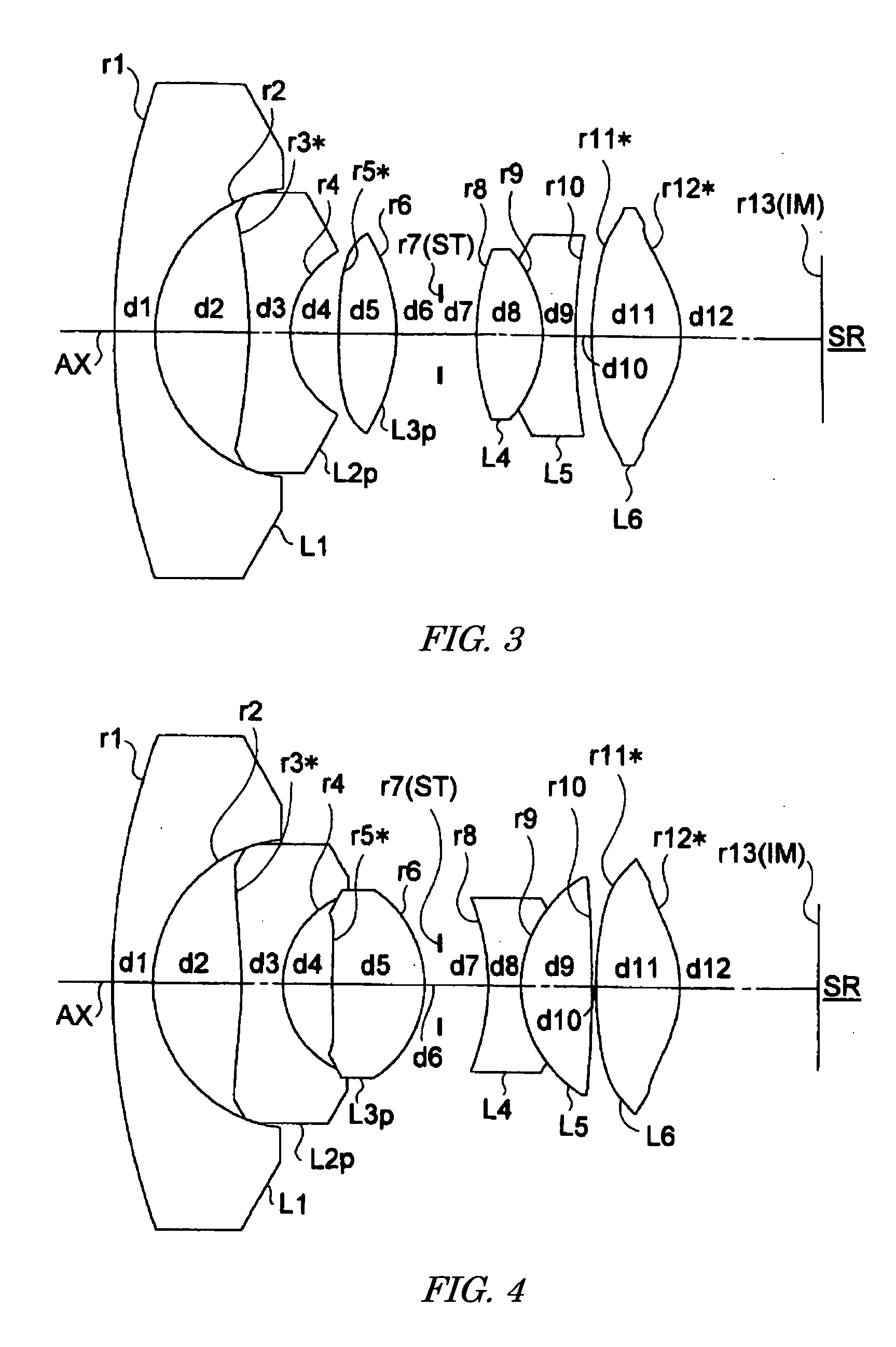
[0085] The super-wide-angle optical system according to the present invention is more concretely explained by exemplifying construction data or the like. The examples 1 to 6 are numerical examples related with the first to sixth embodiments, and the lens constitutional diagrams showing the first to sixth embodiments (FIGS. 1 to 6) illustrate the lens constitutions according to the examples 1 to 6.

[0086] Tables 1 to 6 show the construction data of the first to the sixth examples, respectively. In the construction data of the examples, ri (i=1, 2, 3, . . . ) designates a radius of curvature (mm) of an ith surface counted from an object, and di (i=1, 2, 3, . . . ) designates the ith axial distance (mm) counted from the object. Ni (i=1, 2, . . . ) and vi (i=1, 2, . . . ) designate a refractive index (Nd) with respect to a line d of an ith optical element counted from the object, and an Abbe number (vd), respectively. Further, f designates a focal length (mm) of the entire system, Ψd de...


PUM


Abstract

A super-wide-angle optical system for forming an optical image of an object on an image pickup surface of an image sensing device that converts the optical image into an electrical signal is provided with, in order from the object side, a first negative lens, a second negative lens and a positive lens. The first negative lens has a meniscus shape convex to the object side. The second negative lens is positioned next to the first negative lens. The positive lens has an aspherical surface. At least one of four lens surfaces of the first and second lenses is an aspherical surface. A prescribed condition is fulfilled.

Description

[0001] This application is based on the application No. 2004-31694 filed in Japan, Feb. 9, 2004, the entire content of which is hereby incorporated by reference. BACKGROUND OF THE INVENTION [0002] 1. Field of the Invention [0003] The present invention relates to a super-wide-angle optical system. For example, the invention relates to the compact super-wide-angle optical system having super wide field angle which is suitable for an image input device used as a monitor camera and an in-vehicle camera. Further, the invention relates to an image pickup device using the super-wide-angle optical system. [0004] 2. Description of the Related Art [0005] Since it is necessary for monitor application or the like to pick up ambient image information using small number of image pickup systems extensively, a super-wide-angle optical system for picks up an image of an object at a super wide angle. As such super-wide-angle optical systems, various types of them are conventionally suggested. For exa...

Claims


Application Information

Patent Timeline
IPC IPC(8): G02B13/06G02B13/04G02B13/18H04N5/225
CPCG02B13/06
Inventor OHZAWA, SOHMATSUSAKA, KEIJI
Owner KONICA MINOLTA OPTO
Learn More